
qixinwei-pcba


XY-J02 1-Channel Relay Delay Module Trigger Timer Cycle Switch Board
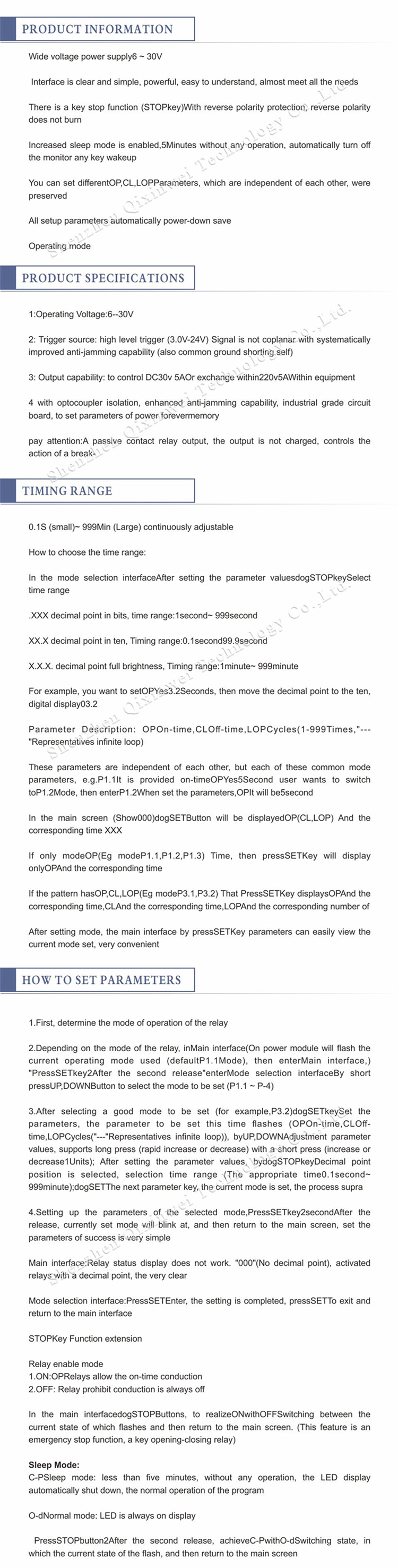
XY-J02 1-channel relay delay module supports delay off, trigger delay, and cycle timing modes. Adjustable timing (0.1s-999min), DC 5V/12V/24V optional. Ideal for light control, motor delay start, water pump timer, automation equipment
XY-J02 1-Channel Relay Delay Module Application features:
◆ Product Model
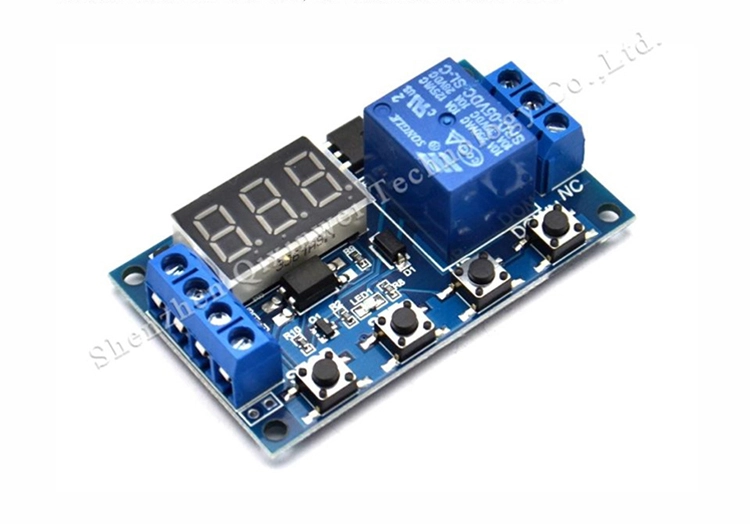
XY-J02 (1-channel relay delay module)
◆ Operating Modes (3 modes)
P1 Mode: Delay off after trigger (signal triggers relay ON, delays then OFF)
P2 Mode: Delay off (relay turns OFF after signal disappears)
P3 Mode: Cycle timing (periodic ON/OFF)
◆ Time Range
0.1 second ~ 999 minutes (adjustable)
◆ Time Setting Method
Onboard buttons + digital display
◆ Supply Voltage (Optional)
DC 5V
DC 12V
DC 24V
◆ Relay Specifications
Contact capacity: 10A 250V AC / 10A 30V DC
Contact type: 1NO + 1NC
◆ Trigger Method
High level trigger (3V-24V compatible)
◆ Display
3-digit digital tube
◆ Dimensions
Approx. 58mm × 36mm
XY-J02 1-Channel Relay Delay Module Typical Applications
Light delay off
Motor delay start
Water pump timing cycle
Exhaust fan timer
Equipment auto power-off
Irrigation timer control
Automation retrofit
XY-J02 1-Channel Relay Delay Module Key Advantages
Three mode switching
Wide adjustable time range
Intuitive digital display
High/low level trigger compatible
Wide voltage supply options
Parameter save on power loss
Why Choose QIXINWEI
Years of experience in the electronics industry. Trusted by global customers.
Massive In-Stock Inventory – Ready to ship promptly
BOM Matching Service – One-stop solution, save time
PCBA Customization – Professional engineering team creates tailor-made solutions based on your needs
Cost-Effective & Efficient – Better channel, better cost
A dedicated team makes your procurement smoother.
Contact us for BOM quotes or PCBA inquiries






FAQ:
1.What is the XY‑J02 relay delay module and its key specifications?
The XY‑J02 is a versatile 1‑channel programmable timer and trigger relay module. It can operate in several modes: delay‑on, delay‑off, cyclic timing, and external trigger. Key specifications: input voltage 5 V – 30 V DC, relay contact rating 10 A at 250 V AC or 10 A at 30 V DC, adjustable timing range from 0.01 seconds up to 999 minutes (user‑selectable), and a built‑in 3‑digit LED display with control buttons. The module is widely used for automating lights, pumps, motors, and industrial equipment where precise timing or triggering is required.
2.How do I power the XY‑J02, and what is the voltage range?
The module accepts a wide DC input voltage of 5 V to 30 V, making it compatible with common power supplies such as 5 V USB, 12 V adapters, 24 V industrial rails, and 3‑series Li‑Ion batteries (9–12.6 V). The input powers both the control logic and the relay coil. Connect DC+ and DC‑ to the power input terminals. The relay output terminals (NO, COM, NC) are galvanically isolated from the control circuit.
3.What are the different operating modes of the XY‑J02?
The XY‑J02 supports four main modes, selected by a button: P‑1: Delay‑on (relay closes after a set time from power‑on); P‑2: Delay‑off (relay opens after a set time from power‑on, then stays off); P‑3: Cyclic mode (relay toggles ON and OFF repeatedly with adjustable ON and OFF times); and P‑4: External trigger with hold‑time (a low‑pulse on the trigger pin energizes the relay for a preset time). These modes make the module extremely flexible for timing, cycling, and trigger‑activated control.
4.How do I set the timing parameters and select the time unit?
The timing is set using the three buttons on the board: SET (to enter programming), UP and DOWN (to change values). After selecting the mode, you can set the ON time and OFF time (for P‑3) or a single delay/hold time (for P‑1, P‑2, P‑4). The time unit is cycled by a long press of SET and can be chosen from seconds, minutes, or hours (display shows “S”, “M”, or “H”). The maximum value is 999 in the selected unit (e.g., 999 seconds, 999 minutes). The digital display clearly shows the current time setting.
5.How does the external trigger input (P‑4 mode) work?
In P‑4 mode, the module acts as a triggerable timer. The TRIG terminal (next to the power input) accepts a low‑level (active‑low) signal. When the TRIG pin is pulled LOW (connected to GND), the relay energizes and stays on for the preset hold time. After the time elapses, the relay turns off automatically, even if the trigger signal remains low. To re‑trigger, the trigger pin must return high and then go low again. This mode is perfect for push‑button controls, sensor‑activated systems, and motion detector outputs.
6.What are the relay specifications and how do I connect the load?
The on‑board relay is a single‑pole double‑throw (SPDT) type, rated at 10 A / 250 V AC and 10 A / 30 V DC. The screw terminals provide NO (normally open), COM (common), and NC (normally closed) contacts. To control a load, connect the power source to COM, and the load to NO (for a circuit that closes when the relay is active) or NC (for a circuit that opens when active). The relay contacts are fully isolated from the low‑voltage control side, with isolation of > 1.5 kV.
7.Can the XY‑J02 be used to create a repeating ON/OFF cycle?
Yes, P‑3 mode is the cyclic timer mode. You can set an ON time (relay energised) and an OFF time (relay de‑energised), and the module will repeat this cycle indefinitely. The times can be set independently, from seconds up to hours. This is ideal for applications such as intermittent pumps, periodic lighting, incubator heaters, and automated irrigation systems where a regular on/off pattern is required.
8.How accurate is the timing, and can the settings be saved during power loss?
The XY‑J02 uses a microcontroller‑based digital timer, providing good accuracy (typically ±1 % over the full temperature range). The module has non‑volatile memory that automatically saves all parameters — mode, time values, and time unit — when they are changed. When power is removed and reapplied, the module resumes operation with the last saved settings, making it reliable for unattended use.
9.What are the most common wiring mistakes that can damage the module?
The most frequent mistakes are reversing the input power polarity (DC+ and DC‑ swapped) — the module does not have reverse‑polarity protection and can be destroyed instantly. Another common error is exceeding the relay contact rating (switching loads over 10 A or 250 V), which can weld the contacts. Also, connecting an inductive load without a snubber or flyback diode can cause voltage spikes that may damage the relay or reset the microcontroller. Always double‑check polarity and use appropriate protection when switching motors or transformers.
10.What are the most typical applications for the XY‑J02 module?
It is extremely popular in home automation (timed lights, fan control), industrial control (motor run‑time limits, conveyor delays), aquarium and hydroponic systems (pump cycling), access control (door lock timers), 3D printer and CNC accessories (light/heater control), and DIY electronics projects. Its simple interface, wide voltage range, and multiple timing modes make it a go‑to timer module for both hobbyists and professionals.
- 原产地:
- Origin
- 品牌:
- Origin
- 型号:
- XY-J02 Relay Module
- 安装方式:
- 表面贴装
- 描述:
- 继电器模块


