
qixinwei-pcba


STM32 Development Board MCU Core Board STM32F4 STM32F411CEU6 STM32F401CCU6 Module
STM32 Development Board Product Overview
The STM32F401/F411 development board is a core board / minimum system board based on STM32F401CCU6 or STM32F411CEU6 chips, featuring ARM Cortex‑M4 core with FPU (Floating Point Unit) for high performance and low power. The F401 runs at 84MHz with 256KB Flash and 64KB SRAM; the F411 runs at 100MHz with 512KB Flash and 128KB SRAM. Onboard 25MHz HSE and 32.768kHz LSE crystals, USB support (virtual COM port / USB disk), reserved Flash pad, and provided USBDisk & FATFS examples. Supports MicroPython firmware. Programming via serial (USART) or DFU mode. Ideal for embedded learning, rapid prototyping, and IoT devices.
STM32 Development Board Core Features
Cortex‑M4 + FPU:32‑bit ARM Cortex‑M4 core with FPU, efficient for DSP and floating‑point tasks. F401 up to 84MHz, F411 up to 100MHz.
Large memory:F401: 256KB Flash + 64KB SRAM; F411: 512KB Flash + 128KB SRAM.
Rich peripherals:USART, I2C, SPI, I2S, ADC, DAC, PWM, USB 2.0 Full Speed. Onboard USB connector (Micro USB/Type‑C).
Onboard resources:25MHz HSE, 32.768kHz LSE, reset button, BOOT0 button, user button, power LED, reserved Flash pad.
Multiple download methods:Serial download (via PA9/PA10) and DFU download (USB directly). Factory pre‑loaded breathing LED + USBDCD demo.
MicroPython support:Ready‑to‑use MicroPython firmware and config files.
Compact size:Core board form factor, can be plugged into breadboard or used as standalone.
STM32 Development Board Applications
Embedded learning & teaching:Suitable for beginners and university courses to learn ARM Cortex‑M4, peripherals, RTOS.
Rapid prototyping:Quick validation via USB download and MicroPython scripting.
IoT nodes:Connect Wi‑Fi/Bluetooth modules, collect sensor data and upload to cloud.
Drone / robot controllers:High‑performance M4 core and rich peripherals for small drones and robots.
USB device development:Emulate USB mass storage, virtual COM port, develop USB audio/HID devices.
STM32 Development Board Key Advantages
The STM32F401/F411 core board offers a low‑cost entry to high‑performance Cortex‑M4 computing. The F411 runs at 100MHz with FPU, capable of medium‑complexity algorithms. Onboard USB supports DFU mode – no external programmer needed. MicroPython firmware makes embedded development accessible to Python programmers. Reserved Flash pad for storage expansion. Factory pre‑loaded demo verifies functionality out‑of‑the‑box. Abundant online STM32 resources and examples drastically shorten project development cycles. Two models: F401 is cost‑effective for general control; F411 doubles Flash and SRAM with higher clock, ideal for larger code or complex computations.
Why Choose QIXINWEI
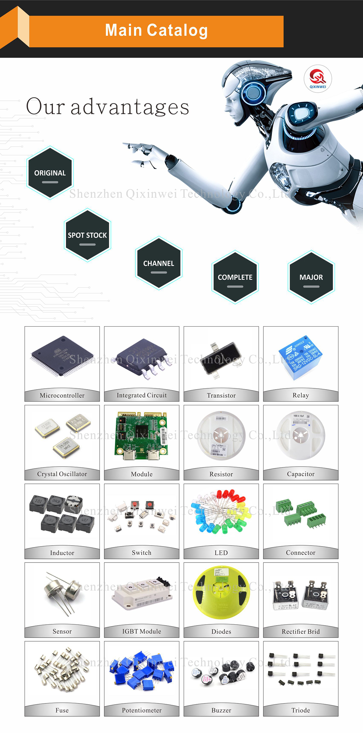
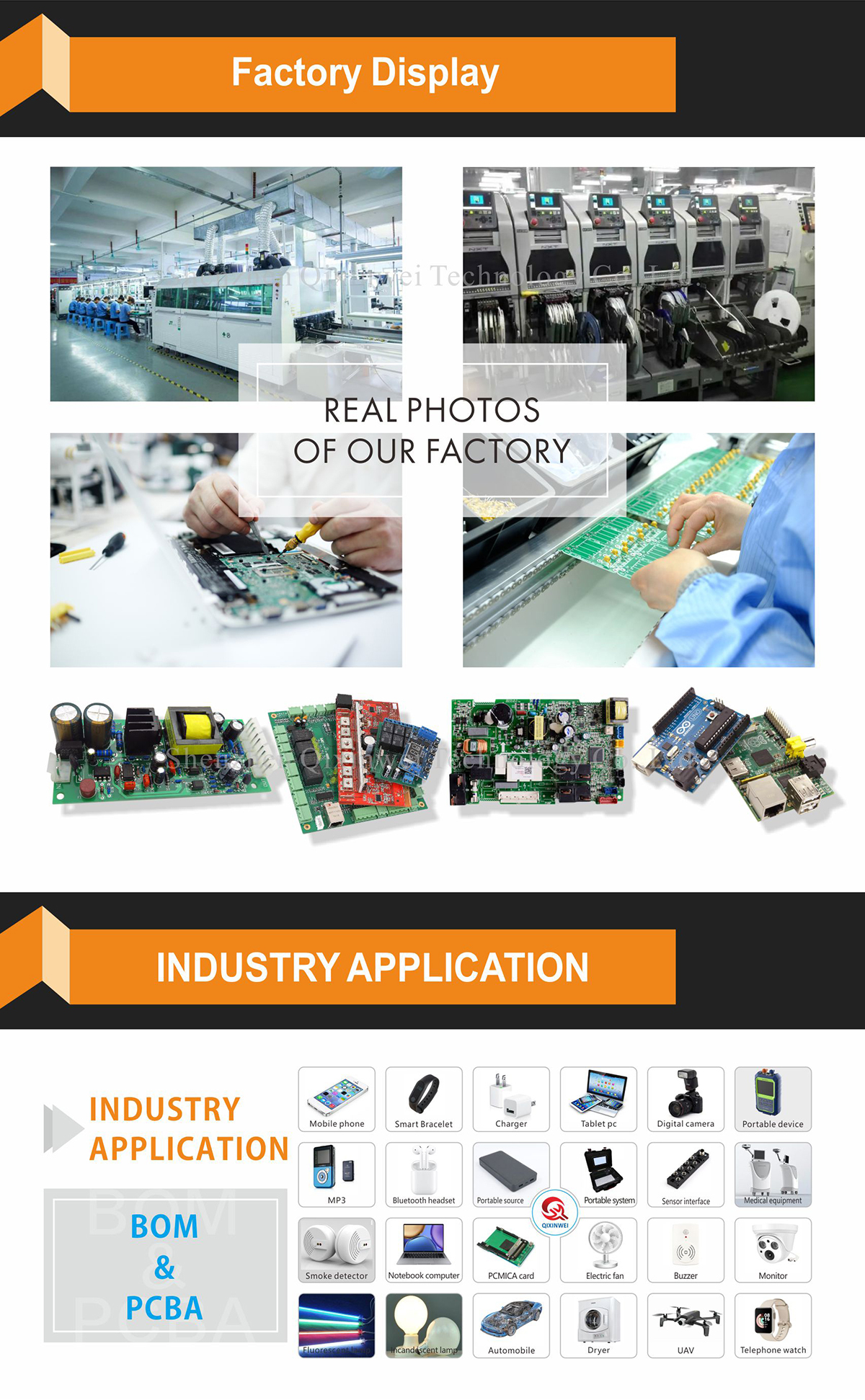
Years of experience in the electronics industry. Trusted by global customers. Massive In-Stock Inventory – Ready to ship promptly. BOM Matching Service – One-stop solution, save time. PCBA Customization – Professional engineering team creates tailor-made solutions based on your needs. Cost-Effective & Efficient – Better channel, better cost. A dedicated team makes your procurement smoother. Contact us for BOM quotes or PCBA inquiries.



FAQ:
What is the STM32F411CEU6 / STM32F401CCU6 "Black Pill" development board?
It is a compact ARM Cortex‑M4F core board that exposes all GPIOs on standard 2.54 mm headers. The board integrates a USB‑to‑UART bridge (CH340 or CP2102), a reset button, a user LED on PC13, and a 3.3 V regulator. It is breadboard‑friendly and can be programmed via the Arduino IDE, PlatformIO, or STM32CubeIDE. Two popular chip variants are the STM32F411CEU6 (100 MHz, 512 KB Flash, 128 KB SRAM) and the STM32F401CCU6 (84 MHz, 256 KB Flash, 64 KB SRAM).How do the STM32F411CEU6 and STM32F401CCU6 differ? Which one should I choose?
The F411CEU6 is faster (100 MHz vs 84 MHz) and has double the Flash (512 KB) and SRAM (128 KB). It also adds an extra SPI and supports up to 5 SPI ports. The F401CCU6 is slightly slower and has half the memory, but it is often more cost‑effective. Choose the F411CEU6 if you need more program space, higher processing speed, or additional SPI interfaces. Choose the F401CCU6 for simpler projects where 256 KB Flash and 64 KB SRAM are sufficient.How do I program this board using the Arduino IDE?
Install the STM32duino package by adding the board manager URL in Arduino IDE preferences. Then install “STM32 MCU based boards” from the Boards Manager. Select “BlackPill F411CE” or “BlackPill F401CC” from the boards list. Connect the board via USB, select the correct COM port, and upload your sketch. The on‑chip USB bootloader (DFU) is also available, allowing firmware upload without an external programmer if the boot pins are correctly set.Is the pinout the same for the F411CEU6 and F401CCU6 Black Pill boards? Can I swap them?
The pinout is almost identical for both versions on the Black Pill form factor. The physical headers and power connections are the same. However, some peripheral functions may be assigned to different pins because the F411 has more SPI ports. Always consult the specific pinout diagram for your board. Mechanically, you can drop one board in place of the other, but verify your sketch’s pin assignments if you change the chip.How do I put the board into DFU (USB bootloader) mode to flash firmware?
Hold the BOOT0 button (or connect BOOT0 to 3.3 V), press and release the RESET button, then release BOOT0. The board will enumerate as “STM32 BOOTLOADER” on your PC. You can then use STM32CubeProgrammer, dfu‑util, or the Arduino IDE (if configured) to upload firmware. This method does not require any external adapter; it uses the on‑chip USB peripheral directly.Are the GPIO pins 5 V tolerant? Can I connect 5 V sensors directly?
No. All GPIOs on both the STM32F411 and STM32F401 are 3.3 V logic only. Applying 5 V to any I/O pin will permanently damage the chip. If you need to interface with 5 V devices, use level shifters or a simple resistive divider. The board itself can be powered from the USB 5 V supply, which is regulated down to 3.3 V by the on‑board LDO.How can I use the built‑in LED? Which pin is it connected to?
On most Black Pill boards, the user LED is connected to PC13 (active‑low). To turn it on, write `digitalWrite(PC13, LOW)`; to turn it off, write `digitalWrite(PC13, HIGH)`. The pin is already defined in the Arduino board package, so you can simply use `LED_BUILTIN` in your sketch. Note that driving this pin high sinks current through the LED, so the logic is inverted.What is the maximum flash and SRAM size on these boards, and can I expand it?
The STM32F411CEU6 provides 512 KB Flash and 128 KB SRAM, while the STM32F401CCU6 provides 256 KB Flash and 64 KB SRAM. Neither chip supports external parallel memory (no FMC), but you can add an external SPI Flash or SPI PSRAM through the SPI pins if more storage or RAM is needed. The internal memory is sufficient for most Arduino‑based projects.Does the board have a crystal oscillator? What is the system clock source?
Yes, the board includes a high‑speed external (HSE) crystal, typically 25 MHz, which provides a precise clock for the main PLL. This allows both chips to run at their maximum rated frequency (100 MHz for F411, 84 MHz for F401). The low‑speed external (LSE) crystal (32.768 kHz) is not populated on most boards, but the internal RC oscillator can be used for the RTC if needed.What are the most common applications for these STM32F4 core boards?
They are used for USB audio devices, virtual COM ports, data loggers, small motor controllers, IoT sensor nodes, and as a general‑purpose upgrade from Arduino Uno or Mega. Their compact size, built‑in USB bootloader, and Arduino compatibility make them a popular choice for both beginners and experienced developers who need more processing power than an 8‑bit MCU.
- Chip Model:
- STM32F401CCU6 / STM32F411CEU6
- Core:
- ARM Cortex-M4
- Frequency:
- F401 up to 84MHz; F411 up to 100MHz
- Memory:
- F401 256KB Flash + 64KB SRAM; F411 512KB Flash + 128KB SRAM
- USB Connector:
- Micro or Type‑C
- Buttons:
- Reset, BOOT0, User button
- Onboard LED:
- Power LED + programmable LED
- Debug Interface:
- SWD
- Power:
- 5V via USB, onboard 3.3V LDO
- Applications:
- Embedded learning, IoT, robotics, USB device development


