
qixinwei-pcba


STM32F303RBT6 ST Mainstream Arm Cortex-M4 Mixed-Signal 32-bit MCU 128KB Flash 72MHz FPU CAN ADC DAC Op-Amp LQFP-64
STM32F303RBT6 Product Overview
The STM32F303RBT6 is a Cortex-M4 mixed-signal MCU from STMicroelectronics in an LQFP-64 package. It runs at 72 MHz with FPU and ART Accelerator. It integrates 128 KB Flash, 32 KB SRAM, CAN 2.0B, USB 2.0 FS (crystal-less), 4×12-bit ADCs (15ch, 0.2µs), 12-bit DAC (2ch), 7 ultra-fast comparators (25ns), 4 programmable op-amps (PGA), up to 11 timers (incl. 2 motor control PWM/deadtime), and up to 15 communication interfaces (3×USART/3×UART/3×SPI/I2S/2×I2C/USB/CAN). 51 I/Os, all 5 V-tolerant. Supply 2.0–3.6 V, -40–85 °C. Compared to the STM32F303CBT6, the package is upgraded to LQFP-64 with more I/Os, while analog peripheral configuration remains identical, suitable for applications needing more I/Os and multi-channel analog front-ends. Compared to the STM32F302RBT6, analog peripherals are significantly enhanced: ADCs increase from 1 to 4, comparators from 3 to 7, and op-amps from 1 to 4, making it ideal for digital power and precision motor control.
STM32F303RBT6 Core Features
Core: Arm Cortex-M4 72 MHz + FPU + ART Accelerator Memory: 128 KB Flash, 32 KB SRAM CAN 2.0B + USB 2.0 FS: Crystal-less USB, LPM and BCD support 4×12-bit ADCs: 15 channels, 0.2 µs, 0–3.6 V 12-bit DAC: 2 channels, buffered 7 Ultra-Fast Comparators: 25 ns 4 Programmable Op-Amps (PGA): Gain ×2/×4/×8/×16 Timers: 2× motor control PWM (deadtime/emergency stop), 3× 16-bit GP, 1× 32-bit GP, 2× watchdogs, SysTick Communication Interfaces: 3×USART + 3×UART (ISO7816/LIN/IrDA), 3×SPI/I2S, 2×I2C (SMBus), USB FS, CAN 2.0B I/Os: 51, all 5 V-tolerant Low Power: Sleep/Stop/Standby, VBAT backup RTC Package: LQFP-64 (10×10×1.4 mm)
STM32F303RBT6 Applications
Digital Power: SMPS, inverters, PFC Motor Control: Dual-motor FOC (2 advanced timers), BLDC/PMSM, fans, pumps Industrial Automation: CAN bus nodes, inverters Consumer: Game controllers, remote controls IoT Nodes Sensor Signal Conditioning
STM32F303RBT6 Key Advantages
Cortex-M4 + FPU + Op-Amps/Comparators + CAN: Extremely high mixed-signal integration for digital power, motor control, and industrial communication 128 KB Flash + 32 KB SRAM: Meets medium-complexity application demands LQFP-64 Package: 51 I/Os, rich resources 4 ADCs + 4 PGAs + 7 Comparators: Rich analog peripherals, no external op-amps/comparators needed, saves significant BOM Dual Advanced Timers: Supports dual-motor FOC 72 MHz FPU: Single-cycle DSP and floating-point operations Crystal-less USB + CAN 2.0B: Combines industrial bus and general communication ADC 0.2 µs Fast Conversion Mature STM32 Ecosystem: CubeIDE/CubeMX/HAL/LL
Why Choose QIXINWEI
Years of experience in the electronics industry. Trusted by global customers.
Massive In-Stock Inventory – Ready to ship promptly.
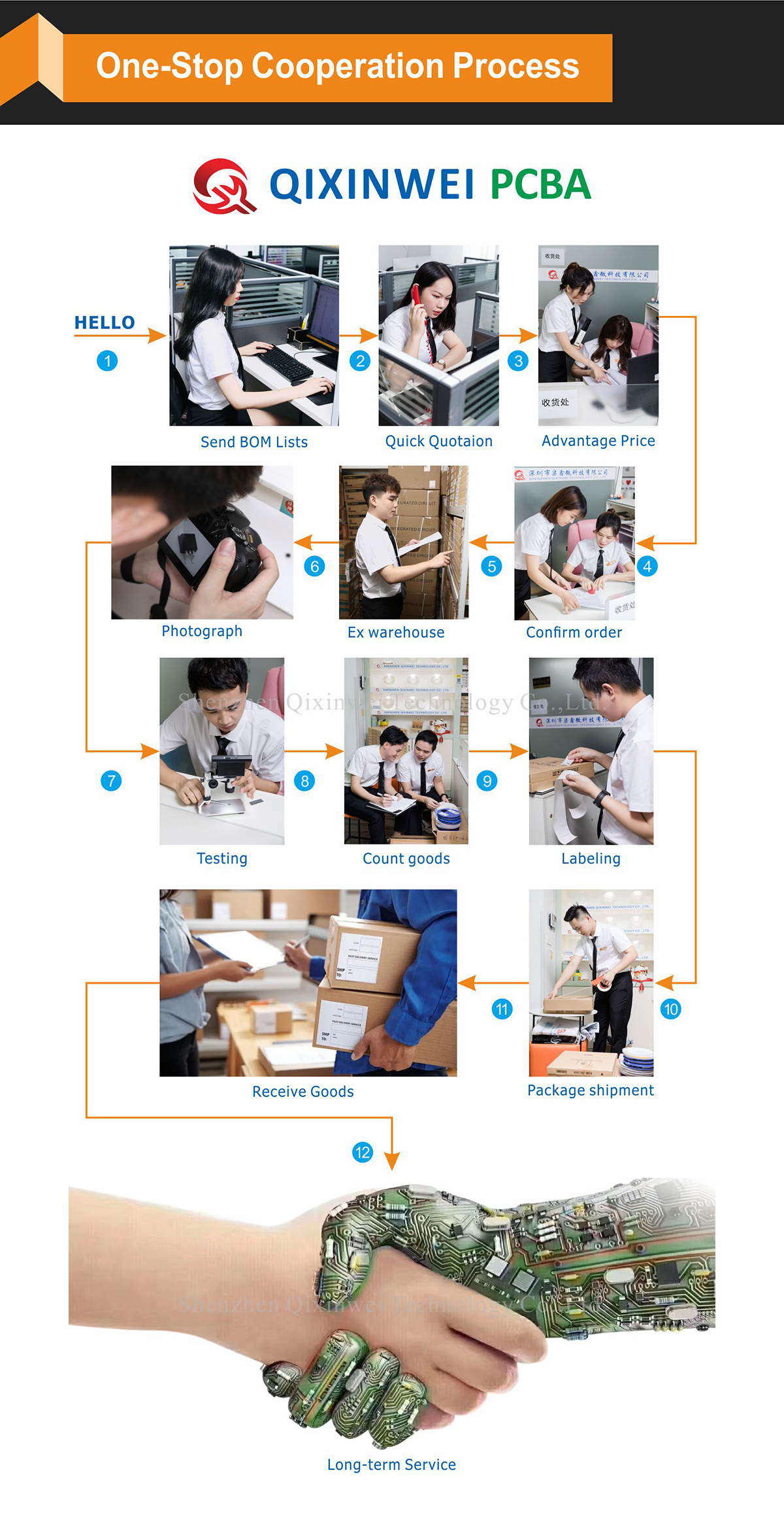
BOM Matching Service – One-stop solution, save time.
PCBA Customization – Professional engineering team creates tailor-made solutions based on your needs.
Cost-Effective & Efficient – Better channel, better cost.
A dedicated team makes your procurement smoother.
Contact us for BOM quotes or PCBA inquiries.






FAQ:
What is the STM32F303RBT6 and how does it differ from the STM32F303RCT6?
The STM32F303RBT6 is a 72 MHz Arm Cortex‑M4F microcontroller with 128 KB Flash and 32 KB SRAM (including a small CCM block for zero‑wait‑state access), packed in an LQFP‑64 package. It retains the same high‑speed analog front‑end as the larger RCT6: four 5 Msps 12‑bit ADCs, two DACs, seven comparators, and four PGAs, plus CAN and USB. The only difference is memory—the RCT6 doubles Flash to 256 KB and expands SRAM to 48 KB. Choose the RBT6 when your code fits comfortably in 128 KB and you want the most cost‑effective entry point into the F303’s powerful analog and motor‑control capabilities, with no compromises on the analog hardware itself.Can 128 KB Flash and 32 KB SRAM really run a complete FOC motor control loop with CAN and USB communication?
Absolutely. A typical field‑oriented control (FOC) library, CANopen stack, and USB device stack fit in under 100 KB, leaving plenty of room for your application logic. The 32 KB SRAM—part of which can be configured as zero‑wait‑state CCM for critical real‑time variables—provides enough space for sensor data buffers, communication stacks, and the control loop. If your firmware later outgrows the 128 KB limit, the pin‑compatible STM32F303RCT6 (256 KB) offers a direct upgrade with no hardware changes.How do the built‑in PGAs and fast comparators simplify a motor‑drive design?
The four embedded programmable gain amplifiers directly interface with shunt resistors for phase‑current measurement, eliminating the need for external op‑amps and their associated passive components. The seven high‑speed analog comparators provide cycle‑by‑cycle over‑current protection without external ICs. This level of integration drastically reduces BOM count and PCB area, which is especially valuable when working with the compact LQFP‑64 footprint.How does the STM32F303RBT6 compare to the classic STM32F103RBT6 as an upgrade?
The STM32F103RBT6 uses a Cortex‑M3 core with a 12‑bit ADC at 1 Msps and no FPU. The F303RBT6 adds a single‑precision FPU, DSP instructions, four 5 Msps ADCs, dual DACs, built‑in PGAs, high‑speed comparators, and a CAN/USB combination. The Flash remains at 128 KB, but the SRAM is increased and a CCM block is added. The pin‑out is often very similar, allowing a smooth hardware migration that dramatically improves control‑loop performance and analog precision for measurement and drive applications.When should I pick the STM32F303RBT6 over the STM32F334 or STM32F302? What is the trade‑off?
The STM32F334 is specialized for digital power with its HRTIM but lacks CAN and has less Flash. The STM32F302 is a lower‑cost analog‑focused device with fewer communication features. The F303RBT6 sits in the perfect middle ground: it delivers the full‑speed analog front‑end of the F303 series, 128 KB of Flash, CAN, USB, and the PGA/comparator chain. Choose it when you need an industrial‑grade mixed‑signal MCU with moderate code size and full communication capabilities, without paying for extra Flash you won't use.Does the STM32F303RBT6 have CCM (Core Coupled Memory), and how should I use it?
Yes, the device includes a small block of CCM that provides zero‑wait‑state access for the CPU. It is ideal for critical real‑time data such as the stack, control‑loop variables, and frequently used lookup tables. DMA cannot access the CCM, so you must place all ADC and communication buffers in the remaining system SRAM. Using the CCM effectively can reduce jitter and improve the determinism of your control algorithm.Can the STM32F303RBT6 run USB and CAN at the same time? What other interfaces are available?
Yes. It includes a full‑speed USB device controller (external pull‑up resistor required; no on‑chip PHY) and a CAN 2.0B interface, both of which can operate concurrently. Additionally, you have three USARTs, two SPIs, and two I2Cs. This makes the RBT6 a capable single‑motor‑drive node that communicates over CAN on an industrial network and over USB for diagnostics or firmware updates—all from a single 64‑pin chip.How fast are the ADCs on the STM32F303RBT6, and can they sample multiple channels simultaneously?
The four 12‑bit ADCs can each achieve up to 5 Msps; in dual‑interleaved mode, two ADCs reach 10 Msps. They support true simultaneous sampling across channels, which is essential for accurate three‑phase current and voltage measurement in motor drives. The ADCs are tightly coupled to the advanced timers, allowing automatic triggering at the PWM center or edge with zero CPU overhead.What development tools and libraries support motor control on the STM32F303RBT6?
All major IDEs—free STM32CubeIDE, Keil MDK, and IAR EWARM—fully support the chip. ST provides the X‑CUBE‑MCSDK with ready‑to‑use FOC and six‑step algorithms optimized for the F303’s fast ADCs and PGAs. You can evaluate on a NUCLEO‑F303RE board (compatible in software) and then migrate to the RBT6 by adjusting the linker script and pin‑out in CubeMX. The STM32CubeF3 package includes comprehensive examples for all peripherals.What are the most typical applications for the STM32F303RBT6?
It is ideal for entry‑level single‑axis motor drives (PMSM/BLDC), digital power converters, compact industrial sensor hubs, multi‑channel data loggers, and any space‑constrained design that needs a fast mixed‑signal MCU with CAN and USB connectivity. The combination of a rich analog front‑end, a cost‑effective 128 KB Flash, and the popular LQFP‑64 package makes it a smart choice for high‑volume and cost‑sensitive professional products.
- Product Type:
- Mainstream Arm Cortex-M4 Mixed-Signal 32-bit MCU
- Brand:
- STMicroelectronics
- Core:
- Arm Cortex-M4 72MHz (FPU + ART Accelerator)
- Package:
- LQFP-64 (10×10×1.4mm)
- Memory:
- 128KB Flash, 32KB SRAM
- Peripherals:
- CAN 2.0B, USB 2.0 FS (crystal-less), 4×12-bit ADCs (15ch/0.2µs), 12-bit DAC (2ch), 7× Ultra-fast comparators (25ns), 4× Programmable op-amps (PGA), 2× Motor control PWM (deadtime), Calendar RTC
- Interfaces:
- 3×USART, 3×UART, 3×SPI/I2S, 2×I2C (SMBus)
- I/Os:
- 51
- Voltage:
- 2.0V~3.6V
- Temperature:
- -40°C~85°C


