
qixinwei-pcba


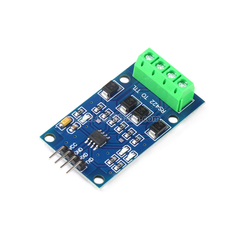
MAX490 RS422 to TTL Module Full Duplex Serial Converter Board for MCU
MAX490 RS422 to TTL Module Application Features:
◆ Main Chip
MAX490 professional full-duplex RS422 transceiver
◆ Signal Conversion
RS422 differential signal ⇄ TTL logic (3.3V/5V compatible)
◆ Communication Mode
Full duplex – transmit and receive simultaneously
◆ Interface Connection
TX → connect to MCU RX
RX → connect to MCU TX
Direct connection to MCU UART
◆ Typical Applications
Industrial field data acquisition
Long-distance serial communication (up to 1200 meters)
PLC to device interconnection
Embedded system debugging
Security monitoring equipment
◆ Key Advantages
Strong anti-interference (differential signaling)
Long transmission distance
No flow control needed, plug-and-play
Compact size for easy integration
Why Choose QIXINWEI
Years of experience in the electronics industry. Trusted by global customers.
Massive In-Stock Inventory – Ready to ship promptly
BOM Matching Service – One-stop solution, save time
PCBA Customization – Professional engineering team creates tailor-made solutions based on your needs
Cost-Effective & Efficient – Better channel, better cost
A dedicated team makes your procurement smoother.
Contact us for BOM quotes or PCBA inquiries




Quantity(Pieces) | 1 ~ 30000 | 30001 ~ 300000 | > 300000 |
Est. Time(days) | 5 | 7 | To be negotiated |

FAQ:
What is the MAX490 RS‑422 to TTL module and its key specifications?
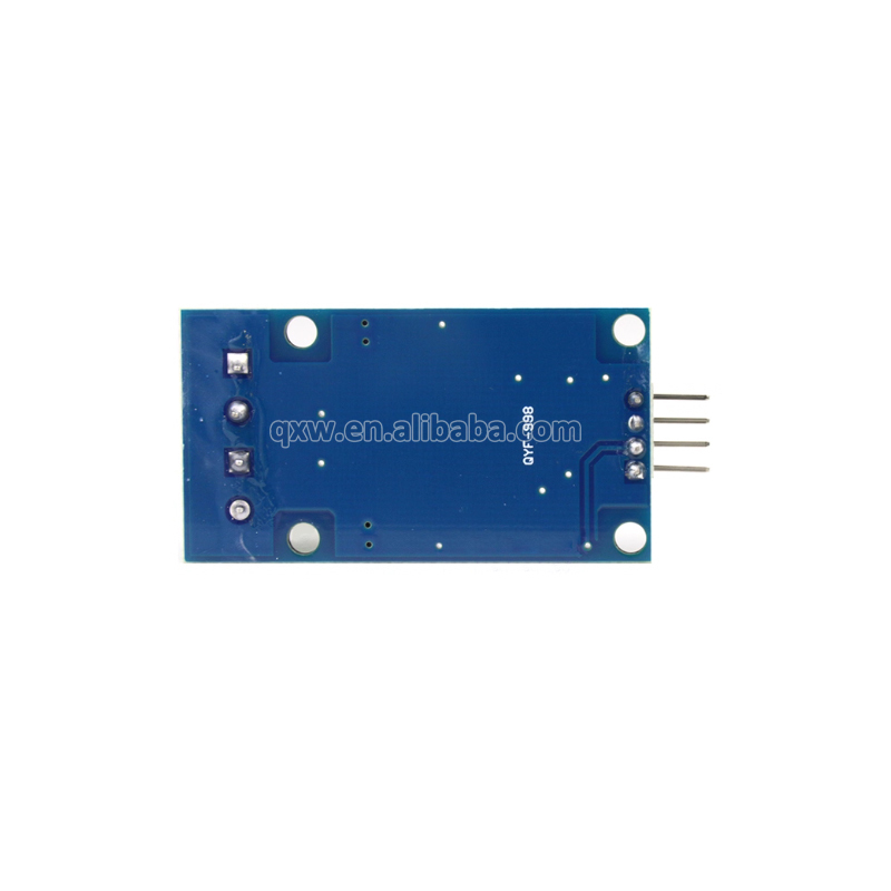
This module is a full‑duplex serial converter built around the Maxim MAX490 low‑power RS‑422/RS‑485 transceiver. It converts TTL‑level (0–5 V) UART signals into differential RS‑422/RS‑485 signals and vice versa. Unlike half‑duplex RS‑485 modules, the MAX490 provides separate transmit (Y, Z) and receive (A, B) pairs, enabling simultaneous bidirectional communication. Key specifications: operating voltage 5 V DC (TTL side), supports data rates up to 2.5 Mbps, allows up to 32 transceivers on a single bus, and features built‑in driver enable (DE) and receiver enable (RE) pins. The module includes screw terminals for the RS‑422 bus and a header for TTL connection, making it ideal for long‑distance industrial communication, PLC interfaces, and MCU serial extension.How do I connect the MAX490 module to an Arduino, ESP32, or other MCU?
Wiring is straightforward. Connect VCC → 5 V, GND → GND, DI (Driver Input) → TX of the MCU, and RO (Receiver Output) → RX of the MCU. The DE (Driver Enable) and RE (Receiver Enable) pins control the data direction. For full‑duplex operation, tie DE HIGH and RE LOW permanently, or connect them to GPIOs if you need to disable the driver/receiver for power saving. On the RS‑422 side, connect the transmit pair (Y, Z) to the receiver’s receive pair (A, B) of the remote device, and vice versa. A 120 Ω termination resistor should be placed across the A and B terminals at both ends of the bus for long cables.What is the difference between the MAX490 and the popular MAX485 module?
The MAX485 is a half‑duplex transceiver that uses a single differential pair (A, B) for both transmit and receive, requiring direction switching via the DE/RE pins. The MAX490 is full‑duplex, providing two independent differential pairs — one for transmit (Y, Z) and one for receive (A, B). This eliminates the need for software direction control and enables true simultaneous two‑way communication. The MAX490 is ideal for point‑to‑point links or star topologies where four wires can be used; the MAX485 is better suited for multi‑drop, 2‑wire buses like Modbus RTU. Both share the same driver and receiver electrical characteristics and can coexist on the same bus if properly configured.What is the maximum communication distance and data rate of the MAX490 module?
According to the RS‑422 standard, the MAX490 can achieve a maximum cable length of 1200 meters (4000 feet) at lower data rates (e.g., 100 kbps). At the maximum data rate of 2.5 Mbps, the distance drops to approximately 100 m – 300 m, depending on cable quality and termination. The module supports baud rates from 1200 bps to 2.5 Mbps. For reliable long‑distance communication, use twisted‑pair cabling (CAT5 or similar), proper 120 Ω termination at both ends, and connect the signal grounds of both devices together through a dedicated wire or the cable shield.How do I use the DE (Driver Enable) and RE (Receiver Enable) pins on the MAX490 module?
The MAX490 provides separate enable pins: DE (active‑high) enables the differential driver (Y, Z outputs), and RE (active‑low) enables the receiver (RO output). For always‑on full‑duplex mode, simply connect DE to VCC (5 V) and RE to GND. This keeps both the transmitter and receiver permanently active, which is the most common configuration for point‑to‑point links. If you need to put the module into a low‑power state or implement hardware flow control, connect DE and RE to separate GPIO pins of your MCU and control them in software.What type of cable should I use with the MAX490 module, and is termination required?
Use a twisted‑pair cable with a characteristic impedance of 100 Ω – 120 Ω, such as standard CAT5/CAT6 Ethernet cable or dedicated RS‑422 data cable. The MAX490 requires two twisted pairs: one for the transmit signals (Y and Z) and one for the receive signals (A and B). For cable runs longer than a few meters, you should install 120 Ω termination resistors across the A/B pair and the Y/Z pair at both ends of the bus to prevent signal reflections. Many MAX490 modules have solder pads for these resistors, or you can add them externally across the screw terminals.Can I use the MAX490 module to build a multi‑drop RS‑422 network?
RS‑422 is primarily designed for point‑to‑point or multi‑drop (one driver, multiple receivers) topologies. In a multi‑drop setup, one MAX490 transmitter (Y, Z) can drive up to 10 receivers (A, B inputs) connected in parallel. However, only one driver should be active on the bus at any time. If you need multiple drivers on the same bus (true multi‑point), you must switch to RS‑485 (e.g., MAX485), which allows up to 32 transceivers sharing a single differential pair. The MAX490 can be used in such a network by enabling the driver only when transmitting, but a half‑duplex RS‑485 module is generally simpler for multi‑point applications.What is the power supply requirement and typical power consumption of the MAX490 module?
The module operates from a single 5 V DC supply (some boards include an LDO regulator, allowing a wider input range — check your specific board). The MAX490 chip itself draws a very low quiescent current: typically ~300 µA with no load and the driver disabled. When actively driving a terminated bus, the supply current can rise to about 20 mA – 30 mA. The module can be powered directly from the 5 V pin of an Arduino or a regulated power supply. The TTL logic pins are 5 V tolerant and can interface with 3.3 V MCUs; however, the VCC pin must be supplied with 5 V for correct RS‑422 output levels.How can I troubleshoot communication problems with the MAX490 module?
Common issues and solutions:
1) No communication: check that DE is HIGH and RE is LOW, verify TTL TX/RX connections, and ensure the remote device is powered and wired correctly (Y to A, Z to B).
2) Garbled data: mismatched baud rates or incorrect UART settings (data bits, parity, stop bits). Add 120 Ω termination resistors at both ends.
3) Data only flows in one direction: check the DE/RE configuration; if using software control, ensure the direction is switched correctly in your code.
4) Intermittent errors at high speed: use short, high‑quality twisted‑pair cables, avoid running signal cables parallel to power lines, and verify that the supply voltage is stable with adequate decoupling capacitors (10 µF + 0.1 µF near the module).
5) Signal reflections: ensure proper termination — a 120 Ω resistor across A/B and Y/Z at both ends of the longest cable run.What are the most typical applications for the MAX490 RS‑422 to TTL module?
It is widely used in industrial automation (PLC communication, sensor networks), long‑distance serial links for microcontrollers, access control panels, LED display controllers, and scientific instrumentation. Its full‑duplex capability makes it especially suitable for point‑to‑point high‑speed data links where software direction control is undesirable, such as transparent serial bridges, CNC machine interfaces, and real‑time data acquisition systems. The module’s rugged differential signalling ensures reliable communication in electrically noisy environments.


