
qixinwei-pcba


N4DIG08 8CH IO Module TTL to RS485 Modbus RTU Digital Switch for PLC Relay
N4DIG08 8CH IO Module Application features:◆ Model
N4DIG08 / R4DIF08
◆ Operating Voltage
DC 6V ~ 24V (12V typical)
◆ Operating Current
8-16mA
◆ Communication Interface
RS485 (half-duplex)
◆ Communication Protocol
Modbus RTU (Function codes 03, 06, 16 supported)
◆ Default Baud Rate
9600bps (configurable: 1200/2400/4800/19200)
◆ Operating Modes (Jumper Selectable)
Mode 1: 8 inputs
Mode 2: 8 outputs
Mode 3: 4 inputs + 4 outputs
◆ Input Level
Supports 3.3V (LvTTL) / 5V (TTL) / CMOS levels
Low level trigger (default) / High level trigger selectable
◆ Output Level
5V TTL level (low/high configurable)
◆ Parallel Capacity
Up to 247 devices in parallel (Modbus addresses 1-247)
◆ Status Reporting
Default: Query mode (host polling)
Configurable: Auto reporting
◆ Module Dimensions
Approx. 44mm × 31mm × 15mm
◆ Weight
Approx. 12.5g
◆ Typical Applications
PLC digital I/O expansion
TTL to RS485 remote transmission
RS485 remote IO control
Smart home control systems
Industrial automation data acquisition
CCTV PTZ control
- LED matrix control
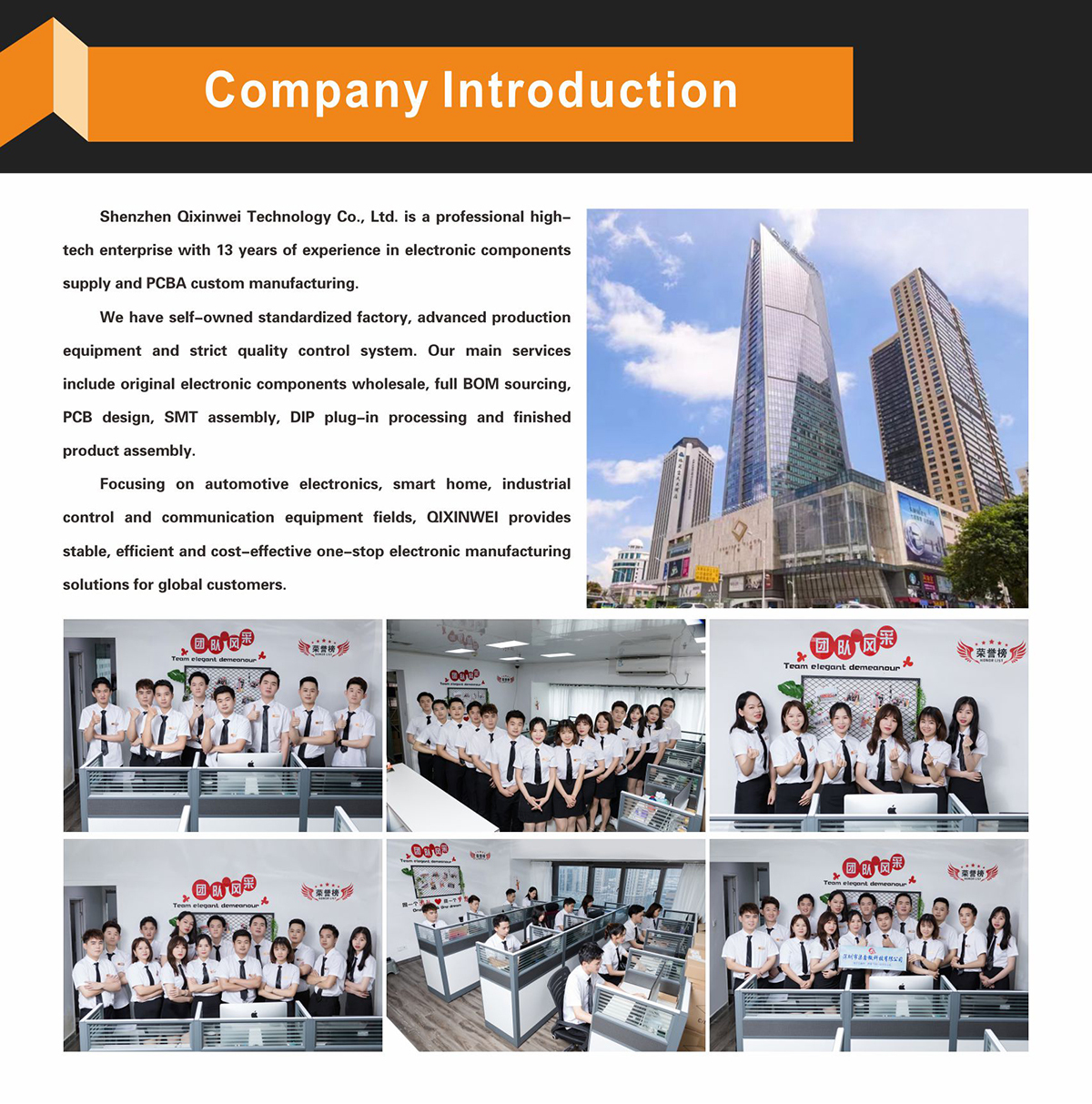
Why Choose QIXINWEI
Years of experience in the electronics industry. Trusted by global customers.
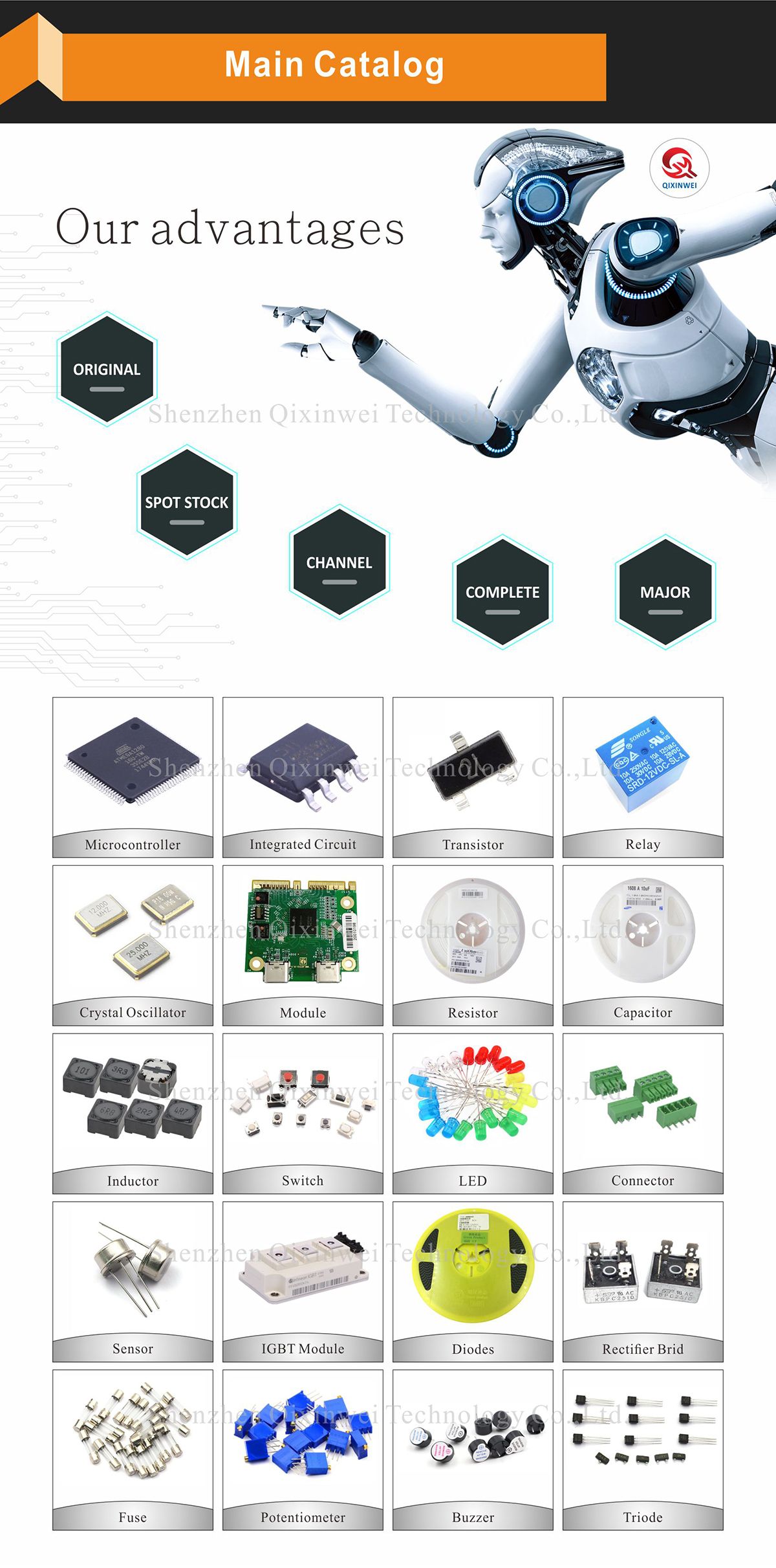
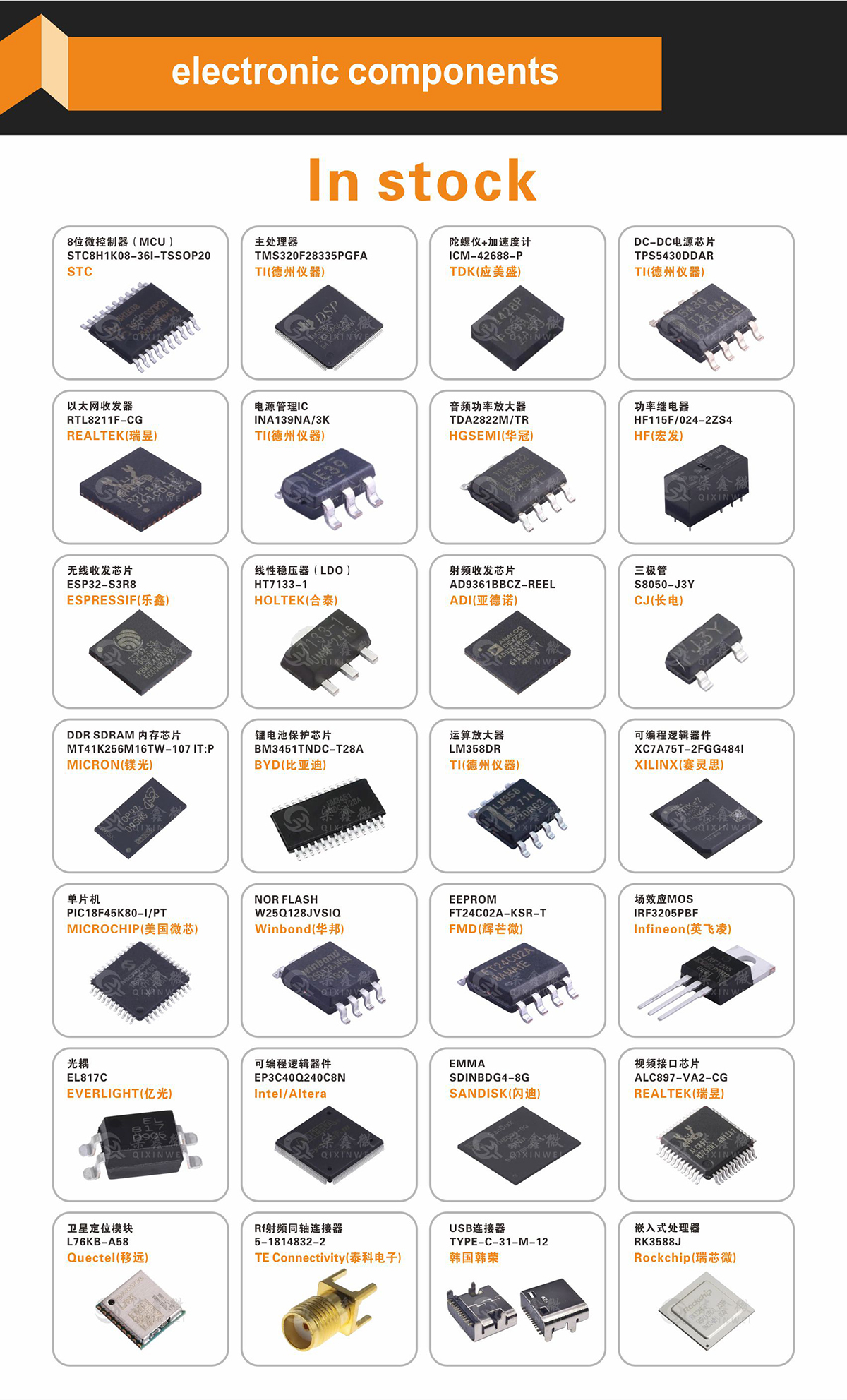
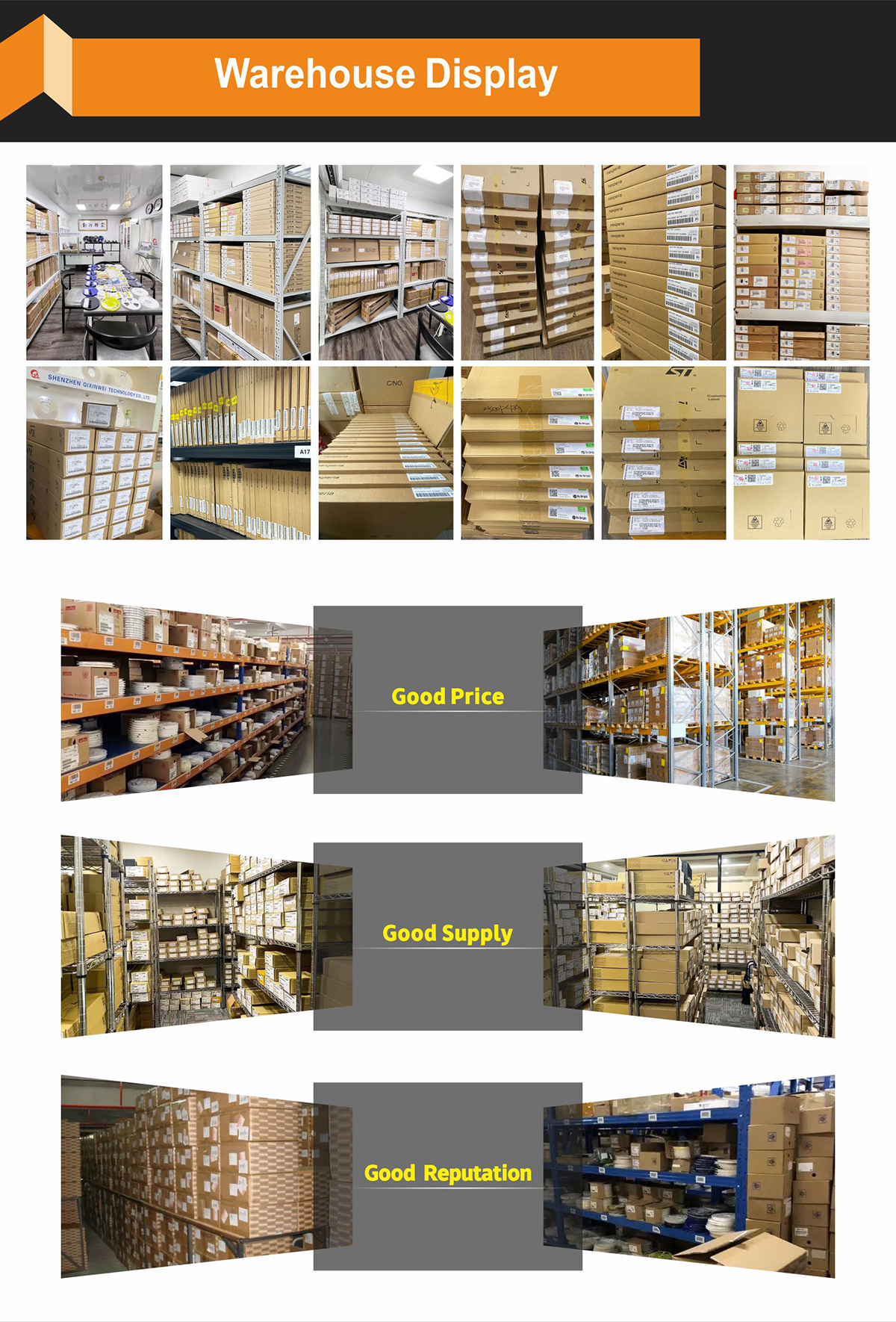
Massive In-Stock Inventory – Ready to ship promptly
BOM Matching Service – One-stop solution, save time
PCBA Customization – Professional engineering team creates tailor-made solutions based on your needs
Cost-Effective & Efficient – Better channel, better cost
A dedicated team makes your procurement smoother.
Contact us for BOM quotes or PCBA inquiries


FAQ:
What is the N4DIG08 8CH IO module and its key specifications?
The N4DIG08 is a compact 8‑channel digital input/output module that bridges TTL‑level (0–5V) signals to an RS485 bus with Modbus RTU protocol. It provides 8 independently configurable digital I/O channels, each usable as an input (dry contact, NPN, PNP) or output (open‑collector, up to 500 mA per channel). The module operates on a wide supply voltage of 5 V – 24 V DC and supports Modbus RTU over RS485 at configurable baud rates from 1200 to 115200 bps (default 9600 bps, 8N1). On‑board photocoupler isolation protects the controller from field‑side noise and surges. It is widely used to expand digital I/Os for PLCs, microcontrollers, and industrial control systems.How do I connect the N4DIG08 to a PLC, Arduino, or ESP32?
Wiring is very simple. Connect VCC and GND to a 5 V – 24 V DC power supply. The RS485 side has A+ and B‑ terminals that connect to the RS485 bus of your PLC or controller. The TTL side (if exposed) can connect directly to an MCU’s UART if you want to talk TTL serial instead of RS485. The 8 digital I/O channels are accessible via screw terminals, each with a COM (common) terminal. For an Arduino or ESP32, you typically connect an RS485‑to‑TTL adapter (like MAX485) between the module and the MCU’s serial pins, or use the on‑board TTL interface if available. Power the module, and use a Modbus master library to read/write the I/O states.What is the difference between the TTL and RS485 interfaces on this module?
The module offers both TTL (0–5V UART) and RS485 interfaces, but only one is active at a time (usually selected by a jumper or by which terminals are used). TTL is convenient for direct connection to a local microcontroller (Arduino, ESP32) at short distances (< 1 m). RS485 is a robust differential bus that can span up to 1200 meters and supports multi‑drop networks (up to 32 devices on a single bus). When using RS485, an external RS485 transceiver (e.g., MAX485) is typically required on the MCU side. The module itself communicates with the same Modbus RTU protocol over either physical layer.How does Modbus RTU communication work on the N4DIG08?
The module acts as a Modbus RTU slave. The host (PLC, PC, or MCU) sends Modbus commands over RS485 to read or write the digital I/O states. The default communication parameters are 9600 bps, 8 data bits, no parity, 1 stop bit (8N1). The Modbus slave address is set by an on‑board DIP switch (typically 1–247). Supported Modbus function codes include 01 (Read Coils), 02 (Read Discrete Inputs), 05 (Write Single Coil), and 15 (Write Multiple Coils). The I/O channels are mapped to Modbus coils (outputs) or discrete inputs (inputs), starting from address 0 (Modbus address 0x0000).What types of digital inputs and outputs does the module support?
Each of the 8 channels can be configured as an input or output via software or jumpers. Input modes: supports dry contact (switch/relay contact between the input terminal and COM), NPN (sinking), and PNP (sourcing) sensors. An internal pull‑up resistor allows direct connection of push‑buttons or limit switches. Output mode: each channel is an open‑collector (NPN) output capable of sinking up to 500 mA at up to 30 V DC. This can directly drive small relays, indicator lamps, or the input of another PLC. For higher‑current loads, an external relay or contactor must be used.Can the N4DIG08 directly drive relays or contactors?
Yes, but only small DC relays with a coil current of less than 500 mA and a voltage up to 30 V DC. The output is an open‑collector transistor that switches the negative side of the load. You must connect the relay coil between a positive DC supply (e.g., 12 V or 24 V) and the output terminal, with a flyback diode across the coil to protect the transistor. For larger contactors, AC loads, or currents above 500 mA, use an external relay module driven by the N4DIG08 output.What power supply does the module require, and what is the typical power consumption?
The N4DIG08 accepts a wide DC input voltage of 5 V to 24 V. Current consumption depends on the number of active outputs: the logic circuit draws about 20 mA – 30 mA, and each output transistor adds a small quiescent current. With all 8 outputs active and driving 20 mA loads each, the total supply current may reach 200 mA – 300 mA. A regulated 12 V or 24 V DC industrial supply is recommended. The on‑board photocoupler isolation separates the control logic from the field I/Os, improving noise immunity.Does the N4DIG08 provide galvanic isolation?
Yes. The module uses optocouplers (photocouplers) on each I/O channel, providing galvanic isolation between the RS485/TTL interface and the field‑side digital signals. The isolation voltage is typically 1500 V – 2500 V for a short duration. This protects the host controller from voltage spikes, ground loops, and electrical noise commonly found in industrial environments. The power supply input is also isolated from the communication side in some designs.How do I configure the Modbus address and communication parameters?
The Modbus slave address (1–247) is set using a 5‑bit DIP switch on the board. Each switch position corresponds to a binary bit, allowing you to select any address in the range. The baud rate and data format (e.g., 9600/8N1, 19200/8E1) are usually configured through a configuration software utility via RS485, or sometimes by another DIP switch bank. After changing the address or baud rate, you must power‑cycle the module. The factory default settings are address 1, 9600 bps, 8N1. Detailed instructions are provided in the module’s user manual.What are the most typical applications for the N4DIG08?
It is widely used in industrial automation to expand the digital I/O count of PLCs and microcontrollers, building automation (lighting and HVAC control), remote data acquisition for sensor and switch monitoring, agricultural control systems (pump and valve control), and alarm and security panels. The module’s ability to communicate over long distances via RS485 and its rugged isolated design make it a go‑to component for distributed digital I/O in harsh environments.
- 原产地:
- China
- 品牌:
- QXW
- 制造商零件编号:
- rs485 io control module
- 产品完成度类型:
- 模块
- 安装方式:
- 表面贴装
- 描述:
- IO控制模块


