
qixinwei-pcba


L9110S Dual Motor Driver Module 2.5-12V 0.8A Dual H-Bridge Smart Car DC/Stepper Motor Driver Board
L9110S Dual Motor Driver Module Product Overview
The L9110S dual motor driver module uses two L9110S H‑bridge driver chips, enabling independent control of two DC motors or one 4‑wire bipolar stepper motor. The supply voltage ranges from 2.5V to 12V, with a continuous current of 0.8A per channel (peak 1.5A). It is suitable for most smart cars and robot cars. The PCB measures only 30×24mm with 3mm mounting holes for easy integration. Control signals are directly from MCU I/O pins (IA1/IB1 for motor A, IA2/IB2 for motor B), allowing forward, reverse, brake, and PWM speed control. Widely used in Arduino smart cars, balancing robots, and DIY projects.
L9110S Dual Motor Driver Module Core Features
Dual independent H‑bridge:Two L9110S chips drive two DC motors or one stepper motor.
Wide supply voltage:2.5V‑12V, compatible with 3.7V Li‑ion, 5V USB, 7.4V Li‑Po, etc.
Output current:0.8A continuous, 1.5A peak – drives TT motors, N20, 130/140 micro motors.
Ultra‑compact size:30×24mm PCB with 3mm mounting holes.
Simple control interface:6‑pin header (VCC, GND, IA1, IB1, IA2, IB2) – direct MCU connection, active low, PWM support.
Green terminal outputs:4‑pin terminal (OA1/OB1, OA2/OB2) for easy motor wiring.
L9110S Dual Motor Driver Module Applications
Smart cars / robots:Drive two DC motors for forward, reverse, turning, differential steering.
Two‑wheel balancing vehicles:With gyroscope and PID for self‑balancing.
Pan‑tilt / camera control:Drive two small motors for pan and tilt.
Stepper motor control:Drive a 4‑wire bipolar stepper motor for 3D printers, small robotic arms.
Toys / DIY projects:RC cars, robot dogs, bionic robots.
L9110S Dual Motor Driver Module Key Advantages
The L9110S dual‑chip module offers higher integration and smaller size than single H‑bridge modules. Wide 2.5‑12V supply voltage supports various battery types. 0.8A continuous current handles common small DC motors. Direct MCU control, no level shifting needed. Onboard mounting holes for easy chassis attachment. Compared to L298N, the L9110S module is over 70% smaller, requires no heatsink, and has simpler circuitry – ideal for DIY cars and mini robots. Low cost, suitable for education, competitions, and high‑volume applications.
Why Choose QIXINWEI
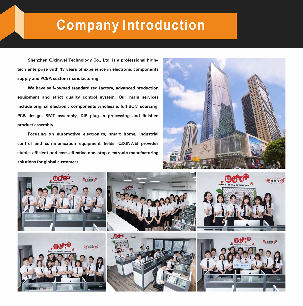
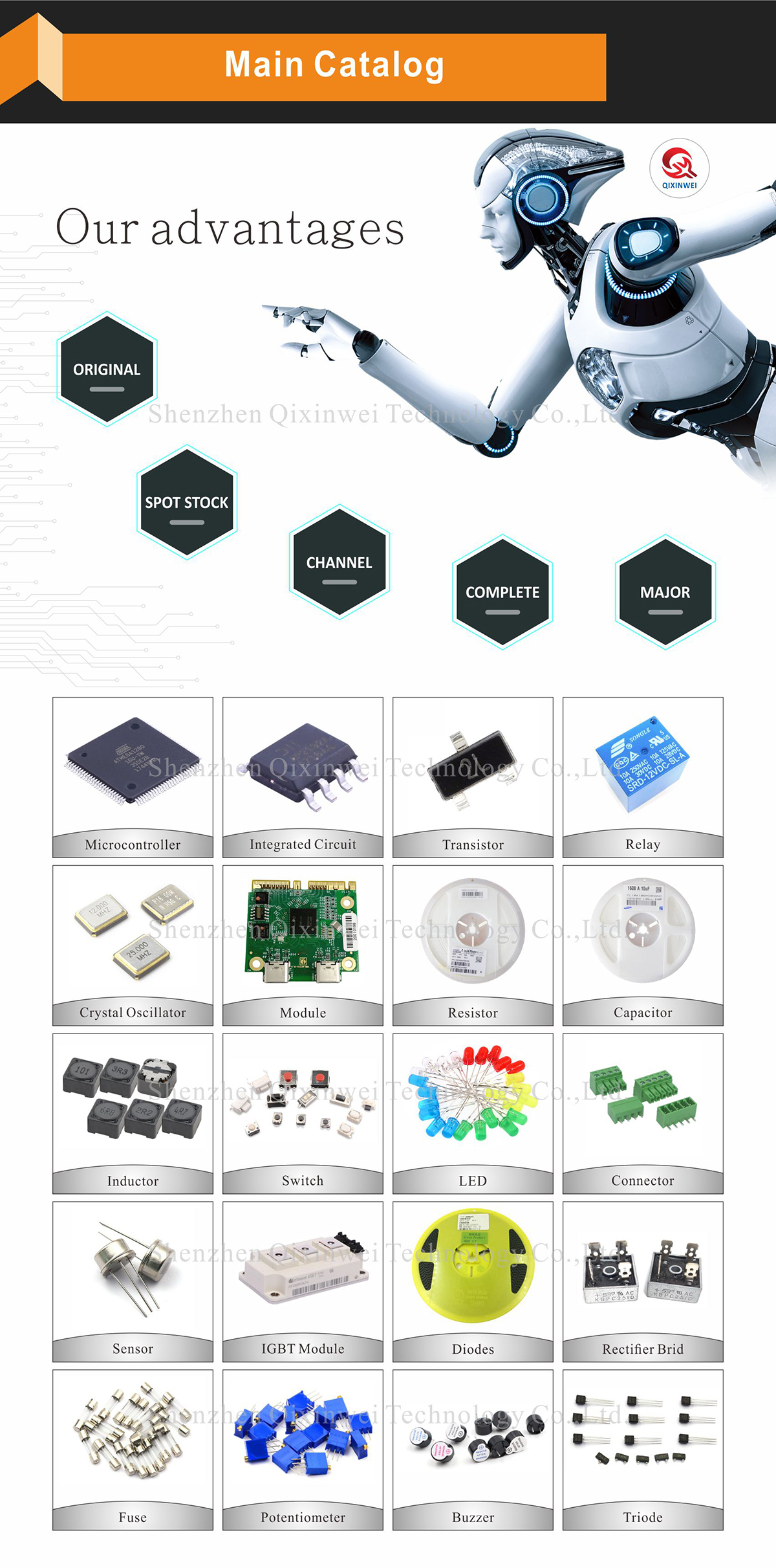
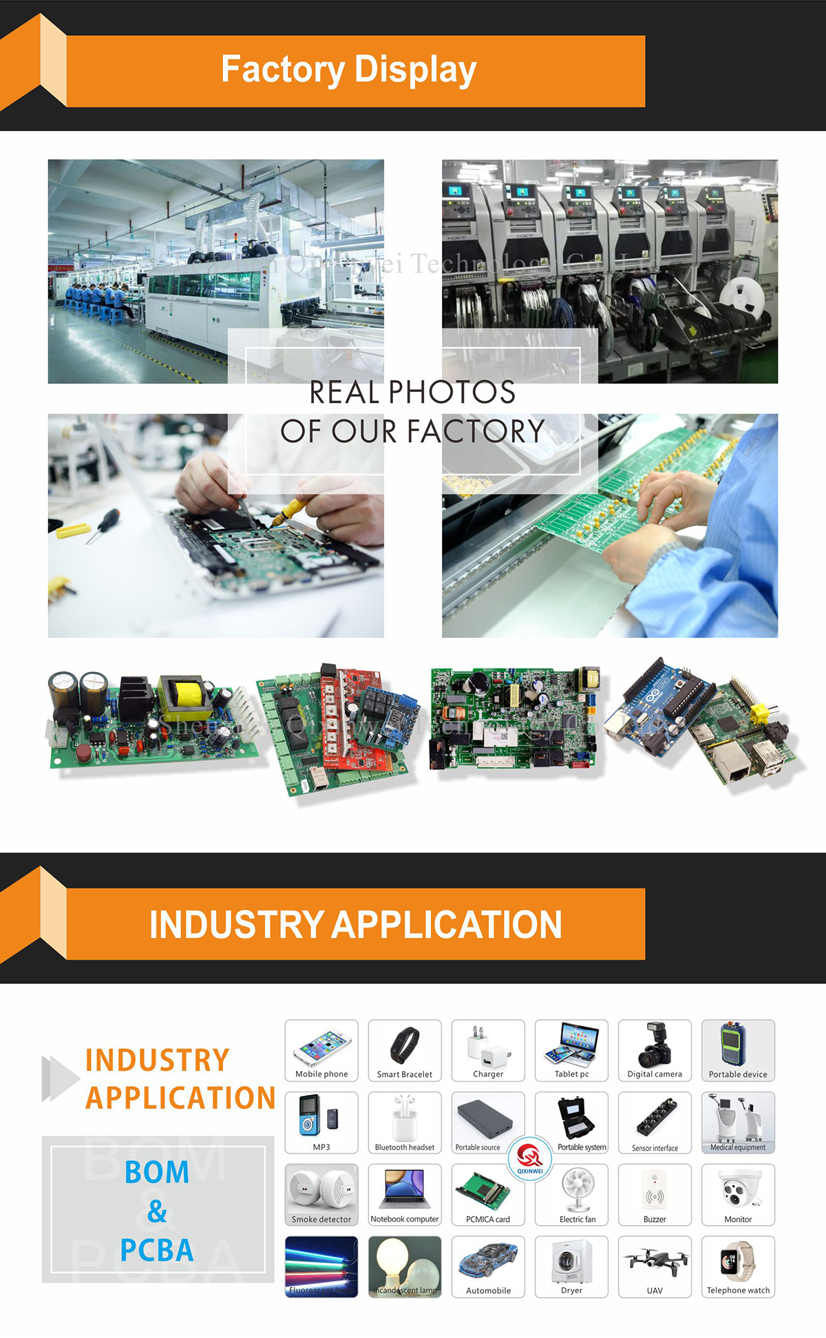
Years of experience in the electronics industry. Trusted by global customers. Massive In-Stock Inventory – Ready to ship promptly. BOM Matching Service – One-stop solution, save time. PCBA Customization – Professional engineering team creates tailor-made solutions based on your needs. Cost-Effective & Efficient – Better channel, better cost. A dedicated team makes your procurement smoother. Contact us for BOM quotes or PCBA inquiries.





FAQ:
What is the L9110S dual motor driver module and what can it control?
The L9110S module is a compact dual H‑bridge driver board based on two L9110S chips. It can independently control two DC motors (bidirectional speed control) or one 4‑wire stepper motor. It is widely used in small robot cars, smart car projects, and other low‑power DC motor applications.What is the operating voltage range and maximum output current of the L9110S module?
The module operates from 2.5 V to 12 V DC. Each channel can deliver up to 800 mA continuous output current, with a peak capability of around 1.5 A for a short period. The actual current depends on the supply voltage and the connected motor load.How do I connect the L9110S module to an Arduino or similar microcontroller?
Connect VCC to the motor power supply (2.5‑12 V) and GND to the common ground. The four control inputs (INA, INB for motor A; INC, IND for motor B) are connected to digital GPIO pins on the microcontroller. The module’s logic is 5 V‑tolerant, so it works directly with 3.3 V or 5 V microcontrollers without level shifting.How do I control the speed and direction of a DC motor using this module?
Direction is set by the logic levels on the input pins: to turn motor A clockwise, set INA = HIGH and INB = LOW; for counter‑clockwise, set INA = LOW and INB = HIGH. Speed is controlled by applying a PWM signal to one of the input pins while keeping the other pin fixed. The L9110S supports direct PWM input without additional circuitry.Can I drive a 4‑wire stepper motor with the L9110S module? How is it wired?
Yes. Connect the two coils of the stepper motor to motor channel A and channel B respectively (e.g., coil 1 to Motor‑A terminals, coil 2 to Motor‑B terminals). Then sequence the four control pins (INA, INB, INC, IND) in the correct step pattern from your microcontroller. The module works with both full‑step and half‑step driving methods.Does the L9110S module require external diodes or heat sinks?
No. Each L9110S chip includes built‑in flyback diodes to protect against inductive voltage spikes from the motor. For typical low‑current applications (under 800 mA), no additional heat sink is required. If the module is operated near its maximum current for extended periods, providing ventilation is recommended.How does the L9110S compare to the L298N motor driver?
The L298N can handle higher currents (up to 2 A per channel) and higher voltages, but it is larger, requires external diodes, and has a higher voltage drop. The L9110S is much smaller, simpler to use, and ideal for low‑power projects. For small DC motors and low‑power stepper motors, the L9110S offers a more compact and cost‑effective solution.Why does my L9110S module get hot, and how can I reduce the heat?
The chip heats up naturally when driving motors, especially at higher currents and voltages. To reduce heat, operate the motors at the lowest voltage that provides adequate torque, limit the continuous current draw, and ensure adequate airflow. If the module becomes too hot to touch, consider reducing the PWM duty cycle or using a separate motor power supply.Can I use this module with a single power supply for both the motors and the microcontroller?
Yes, but with caution. The module shares a common ground with the control logic. If the motor power supply causes noise or voltage dips, it may reset the microcontroller. For reliable operation, especially with larger motors, it is best to use a separate power source for the motors and connect only the grounds together.What are the most common applications of the L9110S dual motor driver module?
It is a favorite for small robotics, Arduino‑based obstacle‑avoidance cars, line‑following robots, automatic curtain controllers, and simple automation projects. Its ability to drive two DC motors or one stepper motor from a single compact board makes it a versatile building block for makers and educators.
- Model:
- L9110S Dual Motor Driver Module
- Type:
- Dual H‑bridge
- Supply Voltage:
- 2.5V – 12V DC
- Continuous Current:
- 0.8A
- Peak Current:
- 1.5A
- Compatible Motors:
- 2 DC motors or 1 bipolar stepper motor
- Control Signal:
- 3.3V/5V TTL
- Speed Control:
- PWM
- Operating Temperature:
- -20℃ ~ +85℃
- Applications:
- Smart cars, robots, pan‑tilt units, stepper motors


