
qixinwei-pcba


GY-87 10DOF Gyroscope Module 3‑Axis Accelerometer+Gyro+Magnetometer+Barometer MPU6050 QMC5883L BMP180 I2C 3‑5V
GY-87 Product Overview
The GY-87 is a high‑precision 10‑degree‑of‑freedom (10DOF) inertial measurement unit (IMU) module that integrates a 3‑axis gyroscope, 3‑axis accelerometer, 3‑axis magnetometer, and barometric pressure/temperature sensor on a single compact board. Featuring an immersion gold PCB finish and onboard logic level conversion circuitry (LLC), it is compatible with both 3.3V and 5V systems. All sensor data is accessible over a single I2C bus.
GY-87 Core Features
The GY‑87 combines three core sensors: the MPU6050 (3‑axis accelerometer + 3‑axis gyroscope with on‑chip DMP), the QMC5883L (3‑axis magnetometer/digital compass), and the BMP180 (barometric pressure + temperature sensor). The MPU6050 acts as the I2C master for the magnetometer, requiring only one I2C address on the host microcontroller.
Each sensor has a unique I2C address: MPU6050 at 0x68, QMC5883L at 0x0D, and BMP180 at 0x77.
Key specifications: gyroscope ranges ±250, ±500, ±1000, ±2000°/s; accelerometer ranges ±2, ±4, ±8, ±16g; magnetometer range ±1.3 to 8 Gauss. Module dimensions are approximately 22×17mm.
GY-87 Applications
Robot navigation and orientation
Attitude and Heading Reference Systems (AHRS)
Motion tracking and gesture detection
Free‑fall detection and 6D orientation detection
GY-87 Key Advantages
The GY‑87 integrates 10 degrees of freedom into a single module with unified I2C access, greatly simplifying hardware design and wiring for multi‑sensor systems. Onboard logic level conversion enables compatibility with both 3.3V and 5V systems. The MPU6050‘s built‑in DMP offloads computation from the host controller. The immersion gold PCB finish ensures reliable solder connections and corrosion resistance. Compared to similar modules, the GY‑87 offers excellent accuracy.
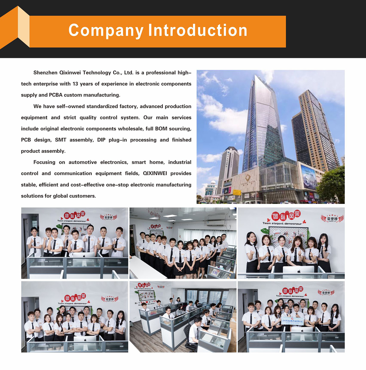
Why Choose QIXINWEI
Years of experience in the electronics industry. Trusted by global customers.
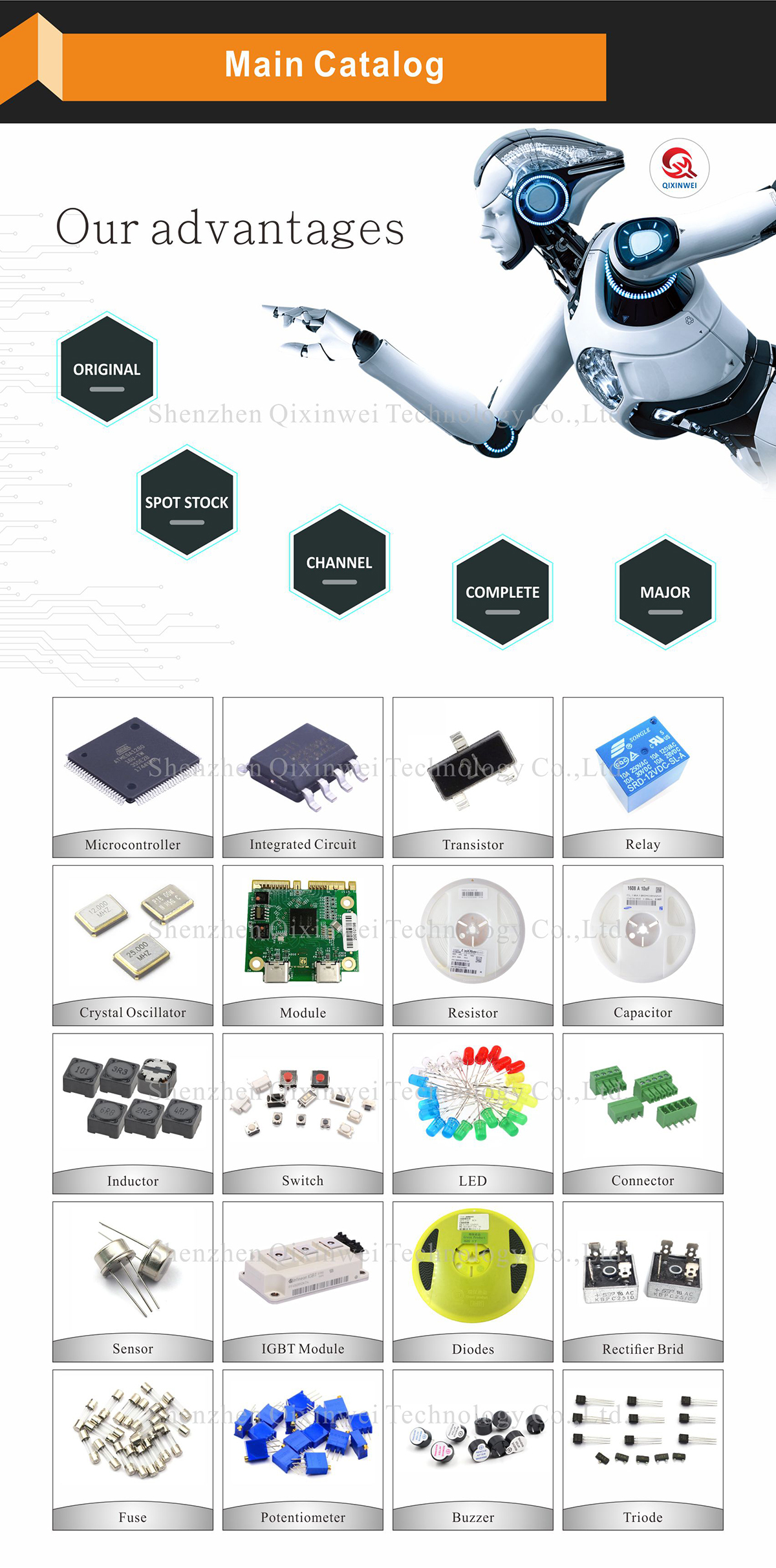
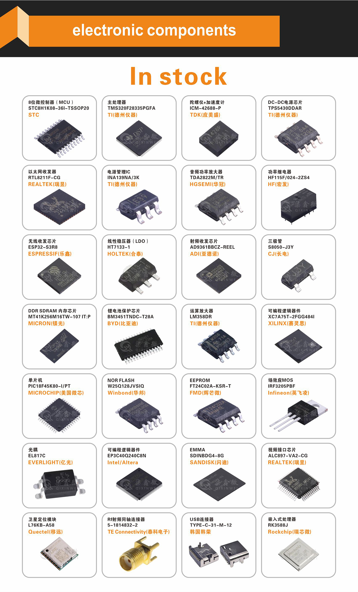
Massive In-Stock Inventory – Ready to ship promptly
BOM Matching Service – One-stop solution, save time
PCBA Customization – Professional engineering team creates tailor-made solutions based on your needs
Cost-Effective & Efficient – Better channel, better cost
A dedicated team makes your procurement smoother.
Contact us for BOM quotes or PCBA inquiries





FAQ
1. What sensors are on the GY‑87 module, and how does it differ from a standard MPU6050 module?
The GY‑87 integrates three independent sensors on a single compact board: the MPU6050 (3‑axis accelerometer + 3‑axis gyroscope), the QMC5883L (3‑axis magnetometer), and the BMP180 (barometric pressure sensor). Compared to a bare MPU6050 module, it adds magnetic field and atmospheric pressure data. The magnetometer compensates for gyroscope Z‑axis drift, enabling a more accurate electronic compass, while the barometer provides altitude measurements—valuable for drone altitude hold, indoor floor detection, and weather monitoring. All sensors share the I2C bus, using only two MCU pins.
2. The module has multiple I2C devices. What are their addresses, and will they conflict?
No, they will not conflict. The three sensors have distinct 7‑bit I2C addresses: the MPU6050 defaults to 0x68 (AD0 pin low), the QMC5883L defaults to 0x0D, and the BMP180 defaults to 0x77. All three can coexist on the same I2C bus simultaneously. An I2C scanner sketch should detect all three addresses. If the MPU6050’s AD0 pin is pulled high, its address changes to 0x69; just ensure it does not overlap with the QMC5883L or BMP180 addresses.
3. How can I read accelerometer, gyroscope, magnetometer, and barometer data at the same time? Is polling required?
All sensors on the GY‑87 support continuous measurement modes, so the host MCU simply reads each sensor’s data registers sequentially over the I2C bus. A typical sequence is: read the MPU6050 acceleration and gyroscope data, then the QMC5883L magnetic field data, and finally the BMP180 pressure and temperature data. I2C communication is fast (100 kHz standard, 400 kHz fast mode), so a complete acquisition cycle takes very little time and easily meets real‑time requirements for attitude calculation and navigation. Placing the read routine in a timer interrupt ensures a fixed sampling interval.
4. How is altitude calculated from the BMP180 barometer, and how accurate is it?
The BMP180 outputs raw pressure values, which can be converted to relative altitude using the standard barometric formula: altitude = 44330 × (1 – (P/P0)^0.1903), where P is the current pressure and P0 is the sea‑level reference pressure (typically 101325 Pa). The module’s relative accuracy is about ±0.12 hPa, corresponding to approximately ±1 meter of altitude difference. Because pressure varies with weather, absolute altitude requires periodic calibration. For indoor floor detection or drone altitude hold, however, short‑term relative changes are very reliable and can clearly distinguish between ascending and descending movements.
5. How should the QMC5883L magnetometer be calibrated, and what is its role in attitude estimation?
The magnetometer measures the Earth’s magnetic field components on three axes, and together with accelerometer data it provides absolute heading (yaw angle). Nearby ferrous materials, motors, and PCB traces, however, introduce hard‑ and soft‑iron distortions that shift and warp the magnetic readings. Calibration is typically performed by rotating the module while collecting sample points, then using ellipse fitting or a least‑squares method to determine offsets and scale factors. Once calibrated, the magnetometer effectively suppresses the gyroscope’s yaw‑axis drift, enabling the electronic compass to maintain accurate heading over time—something a stand‑alone MPU6050 cannot achieve.
6. Does the module support both 3.3 V and 5 V systems? What is the typical power consumption?
The module’s VCC pin accepts 3.3–5 V directly. An on‑board low‑dropout regulator (LDO) converts the input voltage to 3.3 V for the sensors, so no external level shifting is needed whether you are using a 3.3 V STM32/ESP32 or a 5 V Arduino. The I2C lines (SDA, SCL) are pulled up to VCC and are compatible with both logic levels. Total current consumption with all three sensors active is about 5–10 mA, making it well‑suited for battery‑powered drones, wearables, and IoT sensor nodes.
7. Is the MPU6050 on the GY‑87 the same as a stand‑alone MPU6050? Can the DMP still be used?
Hardware‑wise it is identical—the MPU6050 chip on the GY‑87 is the same as on a dedicated MPU6050 module. If your project uses the MPU6050’s built‑in DMP (Digital Motion Processor) for attitude calculation, you can enable it by initializing the MPU6050’s I2C address and loading the DMP firmware as usual. Note that when the DMP is active, it occupies the I2C bus more heavily, which may slightly reduce the read rate for the other sensors (QMC5883L and BMP180). If you use a custom complementary or Kalman filter for attitude, you can simply read raw data from all sensors without the DMP’s involvement.
8. How can the GY‑87 be used to achieve altitude hold on a quadcopter?
The BMP180 barometer provides real‑time altitude information. Because pressure is relatively stable over short periods, the altitude change can serve as feedback for a PID controller. By fusing it with the MPU6050’s vertical acceleration through a complementary filter, you obtain a smooth altitude estimate. Comparing this estimate with the target altitude, the PID output adjusts the throttle to maintain hover. To further improve altitude‑hold accuracy, the accelerometer’s Z‑axis data can be integrated over short periods to limit long‑term drift in the barometer reading.
9. Are there ready‑made libraries for Arduino, ESP32, or STM32 development?
Very mature libraries are available. For the MPU6050, the `MPU6050_light` or `Adafruit MPU6050` libraries are recommended; for the QMC5883L, the `QMC5883LCompass` library; for the BMP180, the `Adafruit BMP085/BMP180` library. All offer concise APIs, allowing initialization, data reading, and calibration with just a few lines of code. To build a complete 10‑DOF attitude solution, you can combine these libraries, sequentially read each sensor inside a timer interrupt, and then run a complementary filter or the Mahony/Madgwick AHRS algorithm.
10. How do I convert the GY‑87’s output into Euler angles? Is an extra algorithm required?
The GY‑87 outputs only raw sensor data (acceleration, angular velocity, magnetic field, pressure). To obtain attitude angles (pitch, roll, yaw), you must run an attitude‑estimation algorithm on the MCU. A common approach is to normalize the accelerometer and magnetometer data, then fuse them with the gyroscope angular velocity using the Mahony or Madgwick AHRS algorithm to obtain a quaternion, which is then converted to Euler angles. The C code for these algorithms is very compact and can easily run in real time at 200–500 Hz on an STM32 or ESP32, providing smooth and stable attitude tracking.
- Model:
- GY-87 10DOF Module
- Sensors:
- MPU6050 (Accel+Gyro) + QMC5883L (Magnetometer) + BMP180 (Barometer)
- Communication:
- I2C
- I2C Addresses:
- MPU6050 0x68, QMC5883L 0x0D, BMP180 0x77
- Supply Voltage:
- 3V – 5V DC
- Gyroscope Ranges:
- ±250, ±500, ±1000, ±2000°/s
- Accelerometer Ranges:
- ±2, ±4, ±8, ±16g
- Magnetometer Range:
- ±1.3 ~ 8 Gauss
- Barometer Range:
- 300 ~ 1100hPa
- Applications:
- Drone flight control, robot navigation, AHRS, motion detection, weather stations


