
qixinwei-pcba


ESP8266 WiFi Relay Module 5V Smart Home Remote Switch Phone App Control ESP01
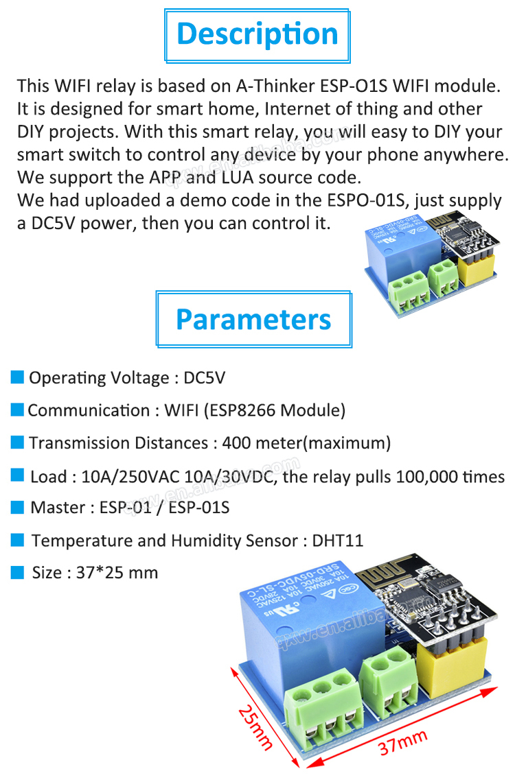
Application features:
◆ Core Module
ESP01 / ESP-01 (ESP8266 WiFi module)
◆ Relay Specifications
Channels: 1 channel
Contact capacity: 10A 250V AC / 10A 30V DC
Contact type: 1NO + 1NC
◆ Supply Voltage
DC 5V
◆ Control Methods
Phone APP (LAN / remote)
Web control
Alexa / Google Home voice control
Timer / countdown
◆ WiFi Frequency
2.4GHz (802.11 b/g/n)
◆ Onboard Resources
Status LED
Reset button
5V relay
Optocoupler isolation (select models)
◆ Pin Definition
DC+ / DC- (power input)
COM / NO / NC (relay contacts)
◆ Control Protocols
TCP/IP
HTTP GET/POST
MQTT (firmware flashable)
◆ Supported Platforms
Android/iOS APP (eWeLink / PointSmart / SmartLife)
Alexa
Google Home
Xiao Ai
Home Assistant
◆ Typical Applications
Smart light control
Remote appliance switch
Garage door remote control
Water pump / motor control
Smart socket DIY
Timer switch
Voice control device
◆ Key Advantages
No programming needed, plug-and-play
Remote control support (anywhere with internet)
Compatible with mainstream voice assistants
Timer / countdown support
Compact size
Secondary development capable (Arduino IDE)




Quantity(Pieces) | 1 ~ 30000 | 30001 ~ 300000 | > 300000 |
Est. Time(days) | 5 | 7 | To be negotiated |

FAQ:
What is the ESP8266 WiFi relay module (5V, ESP‑01) and its key specifications?
This is a compact WiFi‑controlled smart switch that combines an ESP8266 ESP‑01S module with a 5 V relay on a single board. It can switch loads up to 10 A at 250 V AC or 10 A at 30 V DC. The relay is driven by the ESP‑01S’s GPIO2 pin (active‑high). The board includes a 3.3 V regulator to power the ESP‑01S from the 5 V DC input, and exposes UART (TX/RX) pins for programming. It is widely used to control lights, fans, garage doors, and other appliances remotely via WiFi, with support for popular firmware like Tasmota, ESPHome, and Arduino sketches.How do I connect the module and what is the pinout?
The board has a 4‑pin input header: VCC (5 V), GND, RX, and TX. Connect a 5 V DC power supply to VCC and GND; the on‑board regulator provides 3.3 V to the ESP‑01S. The relay output is accessible through a 3‑terminal screw block: NO (normally open), COM (common), and NC (normally closed). The UART pins are used only for programming; during normal operation, the module can run standalone once configured. The relay is controlled by GPIO2 — when GPIO2 goes HIGH, the relay energises, connecting COM to NO.How do I program the ESP‑01S on this relay board with Tasmota, ESPHome, or Arduino?
You need a USB‑to‑serial adapter (3.3 V) or a dedicated ESP‑01 programmer. Connect VCC (3.3 V), GND, TX‑to‑RX, RX‑to‑TX between the adapter and the module. To enter flash mode, pull GPIO0 (IO0) to GND while powering up. Then use Tasmota Web Installer, ESPHome Flasher, or Arduino IDE (with the ESP8266 board package) to upload firmware. Once flashed, remove the GPIO0 jumper and reboot. The relay can then be controlled via MQTT, HTTP, or a local web interface depending on the chosen firmware.How can I control the relay remotely via WiFi, MQTT, or HTTP?
After installing firmware like Tasmota, the module connects to your WiFi network. You can toggle the relay with a simple HTTP GET request (e.g.,http://<ip>/cm?cmnd=Power%20TOGGLE) or via MQTT by publishing a message to the device's command topic. The relay status is reported back, allowing you to build web dashboards, smartphone apps, or integrate with automation platforms. No cloud account is required; everything runs locally on your network.Can this module integrate with Home Assistant, Alexa, or Google Home?
Yes, it integrates seamlessly. With Tasmota or ESPHome, the module can be auto‑discovered by Home Assistant through MQTT or the native API. Using emulated Hue or MQTT‑based plugins, you can also control it with Amazon Alexa and Google Assistant via a local server. ESPHome offers direct Home Assistant integration without MQTT. This turns a low‑cost relay into a fully voice‑controlled smart switch.What is the maximum voltage and current the relay can switch?
The relay is rated for 10 A at 250 V AC and 10 A at 30 V DC. It can safely control most household lights, fans, small motors, and resistive loads. For inductive loads (motors, transformers), de‑rate the current or add a snubber circuit to protect the relay contacts. The relay contacts are galvanically isolated from the low‑voltage side, providing > 1.5 kV isolation.What power supply does the module need, and how is the ESP‑01S powered?
The board requires a 5 V DC power supply (≥ 500 mA recommended). The on‑board AMS1117‑3.3 regulator steps this down to 3.3 V for the ESP‑01S. The relay coil draws about 70 mA when active, and the ESP‑01S peaks around 300 mA during WiFi transmission. A stable 5 V supply is essential; a USB charger or a simple phone adapter works well.How do I put the ESP‑01S into flash mode to upload firmware?
To enter flash mode, you must pull GPIO0 (IO0) to GND while the module is powered on. On the relay board, this is usually done by bridging a solder jumper or connecting a wire between the GPIO0 pin and GND. After the firmware upload is complete, remove the GPIO0‑GND connection and power‑cycle the board. The relay board is designed so that GPIO2 and GPIO0 are pulled high by default, ensuring normal boot when not in programming mode.Are there any safety precautions when using this relay module?
Yes — the relay terminals carry mains voltage, which can be lethal. Always disconnect power before wiring, use insulated screwdrivers, and mount the board inside a protective enclosure. Do not touch the relay terminals while the circuit is live. The module is not certified for use as a safety device; do not rely on it for life‑critical applications. Ensure the load does not exceed the relay rating, and provide a fuse or circuit breaker in series with the load for over‑current protection.What are the most typical applications for the ESP8266 WiFi relay module?
It is widely used in home automation to control lights, fans, coffee makers, and water heaters remotely. Other common uses include garage door openers, smart garden watering, 3D printer power control, aquarium light timers, and DIY access control. Its small size, low cost, and easy integration with open‑source firmware make it a favourite for both beginners and experienced IoT makers.
- 原产地:
- China
- 品牌:
- QXW
- 制造商零件编号:
- ESP8266 WiFi Relay
- 产品完成度类型:
- 模块
- 安装方式:
- 表面贴装
- 描述:
- 无线WiFi中继模块


