
qixinwei-pcba


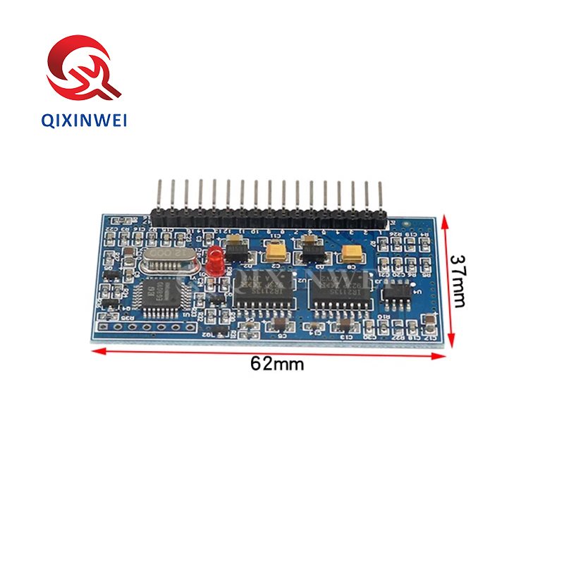
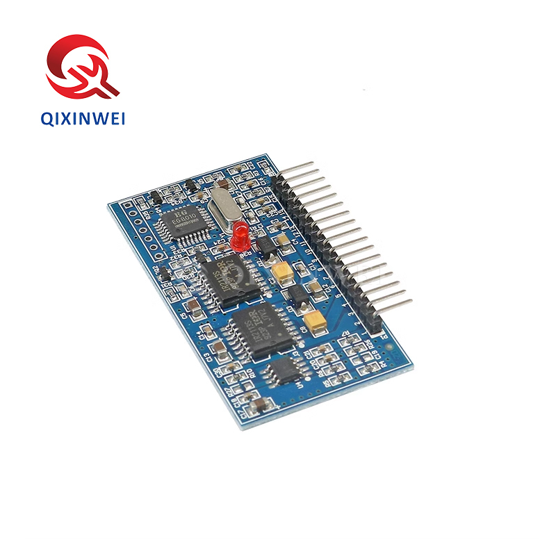
EGS002 EG8010 IR2110 Pure Sine Wave Inverter Driver Board SPWM Module
Application features:
◆ Core Chipset
EG8010: Pure sine wave inverter ASIC
IR2110S/IR2113S: High-voltage high/low-side MOSFET drivers (2x)
◆ Modulation Methods
Unipolar SPWM / Bipolar SPWM (pin configurable)
◆ Operating Voltage
EG8010: 5V single supply
IR2110: 12V supply
◆ Crystal Frequency
12MHz external crystal oscillator
◆ PWM Carrier Frequency
23.4KHz (default)
◆ Output Frequency (Configurable)
50Hz fixed
60Hz fixed
0-100Hz adjustable
0-400Hz adjustable
◆ Dead Time (Configurable)
300ns / 500ns / 1.0μs / 1.5μs (jumper configurable)
◆ Protection Features
Over-voltage protection (OVP)
Under-voltage protection (UVP)
Over-current protection (OCP)
Over-temperature protection (OTP)
◆ Status Indication
3mm red LED warning indicator:
Normal: Steady on
Over-current: 2 blinks / 2s pause
Over-voltage: 3 blinks / 2s pause
Under-voltage: 4 blinks / 2s pause
Over-temperature: 5 blinks / 2s pause
◆ Extended Features
Soft start mode (1s response)
RS232 serial communication (adjustable V/f)
Real-time voltage/current/temperature feedback
◆ Onboard Resources
◆ Typical Applications
Single-phase pure sine wave inverter
Photovoltaic/wind power inverter
Uninterruptible Power Supply (UPS)
Digital generator system
Single-phase motor speed controller
Sine wave dimmer/regulator
Medium frequency power supply
DIY sine wave generator
◆ Key Advantages
No programming required, plug-and-play
Pure sine wave output with SPWM, low THD
Comprehensive protection features
Jumper configurable for flexibility
LCD display expansion
Low cost, easy to use
- Rich community documentation
Why Choose QIXINWEI
Years of experience in the electronics industry. Trusted by global customers.
Massive In-Stock Inventory – Ready to ship promptly
BOM Matching Service – One-stop solution, save time
PCBA Customization – Professional engineering team creates tailor-made solutions based on your needs
Cost-Effective & Efficient – Better channel, better cost
A dedicated team makes your procurement smoother.
Contact us for BOM quotes or PCBA inquiries





Quantity(Pieces) | 1 ~ 30000 | 30001 ~ 300000 | > 300000 |
Est. Time(days) | 5 | 7 | To be negotiated |

FAQ:
What is the EGS002 inverter driver board and its key specifications?
The EGS002 is a pure sine wave inverter driver board based on the EG8010 SPWM controller and IR2110 high‑side/low‑side MOSFET drivers. It generates sinusoidal pulse‑width modulation (SPWM) signals to drive an external full‑bridge or H‑bridge inverter stage. Key specifications: supports 12 V, 24 V, 48 V, and 72 V DC input (depending on external configuration); adjustable output frequency 50 Hz or 60 Hz; carrier frequency 23.4 kHz; built‑in under‑voltage, over‑voltage, over‑current, and over‑temperature protections; LCD display interface for real‑time monitoring; and UART communication for remote control and data logging. The board outputs 4 SPWM signals (high‑side and low‑side) to drive the MOSFET gate drivers, plus feedback pins for voltage, current, and temperature sensing.How does the EGS002 board generate a pure sine wave output?
The EG8010 is a dedicated SPWM (Sinusoidal Pulse‑Width Modulation) controller that uses a look‑up table stored in its internal ROM to generate a precise sine‑wave modulated PWM signal. It outputs four complementary PWM channels (two for each half‑bridge) with adjustable dead time to prevent shoot‑through. These signals are then passed to the IR2110 high‑voltage gate drivers, which level‑shift the logic signals to drive the gates of high‑side and low‑side MOSFETs. When these MOSFETs switch a DC voltage through a step‑up transformer and an LC output filter, the PWM waveform is smoothed into a clean, pure sine wave AC voltage suitable for powering sensitive electronics.What DC input voltage does the EGS002 support, and how do I select it?
The EGS002 board itself is compatible with a wide range of DC input voltages: 12 V, 24 V, 48 V, and 72 V. The specific voltage is selected by a jumper or solder bridge on the board that configures the under‑voltage and over‑voltage protection thresholds. You must also choose the external MOSFETs and transformer rated for your chosen DC voltage. For a 12 V system, you typically use a 12 V battery and a 12 V‑to‑220 V transformer; for 24 V, a 24 V battery, etc. The board's own power supply is regulated by an on‑board LDO that accepts the DC input and provides the required 5 V and 12 V for the logic and gate drivers.How do I adjust the output voltage and frequency of the inverter?
The output voltage is regulated via a feedback loop. A small step‑down transformer or resistor divider senses the AC output and feeds a proportional voltage back to the VFB (voltage feedback) pin of the EG8010. The controller compares this feedback with an internal reference and adjusts the PWM duty cycle to maintain a stable output. The frequency (50 Hz or 60 Hz) is selected by a jumper on the board. Additionally, you can fine‑tune the output voltage using the on‑board potentiometer labelled “VOLT ADJ”. For more advanced control, the UART interface allows you to set parameters such as output voltage, frequency, and protection thresholds via a serial command set.What protection features does the EG8010 controller provide?
The EG8010 includes a comprehensive set of protections: input under‑voltage (UVLO) and over‑voltage protection, output over‑current protection (by monitoring a current shunt), over‑temperature protection (via an NTC thermistor connected to the TFB pin), and soft‑start to limit inrush current. When a fault is detected, the controller shuts down the PWM outputs and can display an error code on the LCD. The board also features a fault output pin that can be used to trigger an external alarm or relay. These protections make the EGS002 suitable for reliable, unattended operation in off‑grid solar systems and backup power supplies.Can the EGS002 drive an H‑bridge directly, or do I need additional components?
The EGS002 provides the low‑voltage SPWM control signals and the IR2110 gate drivers, which can directly drive the gates of external N‑channel MOSFETs. You must supply the power MOSFETs, a transformer, an output LC filter, and a DC input source. The board does not include the MOSFETs themselves. A typical setup uses 4 power MOSFETs in a full‑bridge configuration, with the IR2110 driving the high‑side and low‑side gates. The board also provides bootstrap diodes and capacitors for the high‑side drivers, so you only need to connect the external MOSFETs. For higher power, you can use multiple MOSFETs in parallel or IGBTs, ensuring the gate drive signals are buffered appropriately.What is the purpose of the LCD display and UART interface on the EGS002?
The on‑board LCD connector (for a standard 16×2 character LCD) displays real‑time information such as DC input voltage, output voltage, output current, output power, frequency, and temperature. Error codes are shown when a protection event occurs. The UART interface (TX/RX pins) allows you to connect the board to a microcontroller, PC, or Bluetooth module to remotely monitor and control the inverter. Through simple serial commands, you can read all measurements, change the output frequency, adjust voltage, set protection limits, and even turn the inverter on/off. This makes the EGS002 ideal for smart inverter applications and data logging.How does the EGS002 handle different power levels? What is the maximum power?
The board itself is a low‑power control circuit; the maximum inverter power is determined entirely by the external MOSFETs, transformer, and heatsinking. The EG8010 + IR2110 can drive MOSFETs with gate charges up to several hundred nanocoulombs, enabling inverters from a few hundred watts to several kilowatts. A common design using 4× IRF3205 MOSFETs and a 12 V battery can deliver about 500 W – 1000 W. With higher‑voltage battery banks (48 V) and IGBTs, 3 kW – 5 kW is achievable. The built‑in current sense input allows the controller to limit output current and protect the MOSFETs from overload. Always design the power stage according to your specific power requirements.Why is dead time important in SPWM inverters, and how is it set on the EGS002?
In a half‑bridge or full‑bridge, the high‑side and low‑side MOSFETs must never conduct simultaneously, as this would short the DC supply (shoot‑through) and destroy the transistors. Dead time is a small delay inserted between turning off one MOSFET and turning on the complementary one. The EG8010 provides adjustable dead time, typically set via a jumper or resistor on the EGS002 board. The default dead time is around 300 ns – 500 ns, which is sufficient for most MOSFETs. The IR2110 also has its own shoot‑through prevention logic. Proper dead time ensures safe, efficient switching and prevents overheating. If you use slow MOSFETs or IGBTs, you may need to increase the dead time.What are the most typical applications for the EGS002 inverter driver board?
The EGS002 is extremely popular in DIY pure sine wave inverters for solar off‑grid systems, home backup power, camping/RV inverters, and educational power electronics projects. It is also used in industrial frequency converters, UPS systems, and motor drives where a clean AC output is required. Its low cost, built‑in protections, and easy‑to‑read LCD make it a favourite among hobbyists and small‑scale manufacturers for building reliable, efficient inverters without designing the complex SPWM control from scratch.
- 应用:
- 原标准
- 系列:
- 原标准
- 特征:
- 原标准
- 安装方式:
- 原标准
- 尺寸/尺寸:
- 原标准
- 描述:
- 原标准
- 型号:
- EGS002
- 种类:
- Original standard
- 原产地:
- Afghanistan
- 品牌:
- Original
- 配置:
- 原标准
- 电流:
- 原标准
- 电压:
- 原标准
- 电压 - 隔离:
- 原标准
- 封装/外壳:
- 原标准
- 相似属性可替代料号:
- 原标准
- 零件号:
- EG8010
- Rohs:
- 原件
- 条件:
- 全新和原始
- 工作温度:
- 标准
- 耗散功率:
- 标准
- 电源电压:
- 标准
- 装运方式:
- DHL/UPS/Fedex/EMS/香港邮政
- 付款:
- Paypal,T/T,西联汇款
- 类型:
- 原标准


