Electronic components
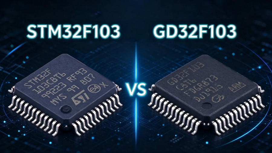
How to choose STM32F103 and GD32F103?
1、Selection Guide for STM32F103 and GD32F103
The relationship between STM32F103 and GD32F103 is often simplified as “original” versus “low-cost alternative.” Hardware-level pin-to-pin compatibility makes board-level replacement look easy—pin definitions for the same model are identical, register address logic is the same, and even ST’s library files can barely compile on GD32. However, between “runs once soldered” and “stable mass production” lie a series of deep differences in clock timing, analog accuracy, and startup behavior.
1.1 Core Parameter Comparison
| Comparison Dimension | STM32F103C8T6 | GD32F103C8T6 |
|---|---|---|
| Core | Cortex-M3 (R1P1) | Cortex-M3 (R2P1) |
| Maximum Clock Frequency | 72 MHz (HSE) | 108 MHz (HSE) |
| Flash | 64 KB | 64 KB (self-developed, 0 wait states @108 MHz) |
| SRAM | 20 KB | 20 KB |
| Operating Voltage | 2.0 V–3.6 V | 2.6 V–3.6 V |
| Package | LQFP-48 | LQFP-48 (pin-to-pin compatible) |
1.2 Interpretation of Key Differences
The “paper advantage” of clock frequency and execution efficiency. GD32’s 108 MHz versus STM32’s 72 MHz is a 50% paper improvement. More critically, there is the Flash wait-state issue: GD32 has 0 wait states for Flash access at 108 MHz, while STM32 requires 2 wait states at 72 MHz. This means that at the same clock frequency (for example, both running at 72 MHz), GD32 code execution may also be faster. In actual measurements, GD32’s GPIO toggle speed can reach 50 MHz, while STM32F103 is about 18 MHz. For screen refreshing, motor control, high-speed communication, and similar scenarios, this is a real benefit.
The “two sides” of power consumption. GD32’s core voltage is lower (1.2 V vs. STM32’s 1.8 V), so power consumption at the same clock frequency is lower (32.4 mA vs. 52 mA). But the situation is exactly the opposite in low-power modes: GD32’s standby current is about 10.5 µA, while STM32’s is only about 3.4 µA; the gap is even larger in deep sleep mode (GD32 about 1.4 mA, STM32 about 24 µA). If your product is battery-powered and spends most of its time sleeping, STM32’s low-power advantage is structural; if the device runs continuously, GD32’s run-power advantage is more meaningful.
Accuracy gap in analog peripherals. GD32’s ADC is nominally 12-bit, but measured effective number of bits (ENOB) is about 10.2 bits, 0.3–0.5 bit lower than the same STM32 model. After migrating some projects from STM32 to GD32, ADC sampling values showed a 2–5 LSB offset, requiring recalibration or adjustment of sampling-time configuration. For high-precision analog acquisition scenarios, this is an area that must be verified carefully.
3、Design Points and Common Errors When Replacing STM32F103 with GD32
3.1 Hardware Design: Three Things That Must Be Changed
BOOT0 must not float. This is the most easily overlooked hardware pitfall in GD32 replacement. STM32’s BOOT0 can run floating, but GD32’s BOOT0 must be connected to GND through a 10 kΩ pull-down resistor; otherwise, the chip may fail to start normally. In one motor control project, BOOT0 was not pulled down, causing frequent system resets; it took a week of debugging to locate the root cause.
The reset circuit cannot be omitted. In some designs, STM32 can omit the external RC reset circuit, but GD32 requires one; otherwise, it may fail to operate normally after power-up.
Handling of pins 31 and 47. Pins 31/47 of GD32 are NC (not connected), while the corresponding STM32 pins are VCAP and require a capacitor to GND. Soldering the capacitor as before will not affect functionality, but it can be removed to simplify the BOM.
3.2 Software Migration: Five High-Frequency Issues
First, the startup file must be replaced. STM32’s cannot be used directly in a GD32 project; the startup file officially provided by GD32 must be used. Incorrect use may cause hardware exceptions that are difficult to locate.
Second, the HSE startup timeout must be increased. GD32’s external crystal startup time is longer than STM32’s. If the default timeout value of the STM32 library is used, the system may hang because it continues execution before the crystal is stable. It is recommended to significantly increase or refer to the recommended value in GD32 official examples.
Third, peripheral configuration must “enable the clock first, then configure.” GD32 has stricter timing requirements than STM32. STM32 allows “write registers first, enable clock later” for some peripherals, but GD32 silently ignores register writes when the clock is not enabled, causing configuration failure that is difficult to troubleshoot.
Fourth, Flash erase and write timing assumptions must be revalidated. GD32’s typical page erase time is about 60 ms, longer than STM32’s 20–40 ms. Hard-coded timeout values in bootloaders, EEPROM emulation layers, and OTA upgrade systems must be relaxed accordingly; otherwise, the next step may be executed before erasure is complete.
Fifth, hardware I2C may have stability issues at 400 kHz. Multiple sources mention that I2C firmware written based on STM32 timing characteristics may encounter communication abnormalities on GD32. A common solution is to switch to software I2C or manually adjust bus timing parameters.
4、Selection Decision: Draw Lines by Scenario, Not by “Domestic/Imported”
Scenarios Where STM32F103 Should Be Firmly Chosen
Low-voltage battery power: The operating voltage needs to be below 2.6 V, so GD32F103 is immediately ruled out.
Precision analog acquisition: ADC ENOB requirements are ≥11 bit, or the signal chain is sensitive to noise and linearity.
Sleep-dominated, long-battery-life devices: µA-level differences in deep sleep are amplified into non-negligible differences in battery life.
Industrial / automotive / medical and other high-reliability fields: STM32’s peripheral consistency, long-term supply record, and failure analysis ecosystem remain more complete.
The product is already in mass production, and the BOM and test system are built around STM32: The hidden validation cost of migration may exceed the material savings.
Scenarios Where GD32F103 Should Be Given Priority
Cost-sensitive, high-volume consumer electronics / general industrial control / IoT terminals: The price of F103 at the same level is about 1/3 to 1/2 of ST’s, and lead times are an order of magnitude shorter.
Need more clock-frequency headroom but do not want to move to M4: 108 MHz is a “free speed boost” for existing M3 code, especially suitable for control loops and polling-intensive tasks.
Supply chain risk is the primary consideration: In an environment where STM32 lead times may still stretch beyond 20 weeks, GD32’s 8–12 week lead times provide planning certainty, not just price.
The team has embedded low-level debugging capability: It can handle startup files, clock trees, Flash timing, and analog front-end adaptation, rather than relying only on “it runs after flashing.”
The “Middle Ground” That Requires Extra Caution
If a project needs both GD32’s cost and analog accuracy and industrial reliability close to STM32’s, GD32F103 may not be the endpoint. It is worth looking at the GD32E series (some models are optimized in power consumption and accuracy) or domestic alternatives at the same level such as APM32 and AT32. These have different emphases in industrial reliability or code migration compatibility, but that is the subject of another selection article.
5、Project Cases: Practical Records of Replacing STM32F103 with GD32
Control Period Comparison on a Stepper Motor Driver Board
In a stepper motor driver project, after replacing STM32 with GD32, the control period changed from 1.8 ms to 1.83 ms, with an error within ±0.5%. For most industrial scenarios, this deviation is fully acceptable. The PWM waveform jitter generated by GD32’s TIM1 at 108 MHz was 0.3% smaller than that of STM32 at 72 MHz, indicating that in motor control applications, GD32’s clock-frequency advantage and timer performance can translate into real benefits.
Cost-Driven Migration of a Smart Home Controller
A smart home controller originally used STM32F103C8T6 and was migrated to GD32F303CCT6 due to cost pressure and supply chain risk. F303 was chosen instead of F103 because F303 offers an M4 core and richer peripherals while maintaining compatibility, and the BOM cost remained acceptable. The lesson from this case is that GD32’s product line also has tiers: F103 is suitable for basic replacement, while F303/E103 provides a “compatible upgrade” path.
6、Application Scenarios
GD32’s advantageous scenarios are concentrated at the intersection of “cost-sensitive + continuous operation + performance demand.” Consumer electronics (small appliance control, toys, LED drivers), industrial auxiliary control (non-safety-critical motor drives, sensor nodes), and high-volume IoT terminals are typical battlegrounds for GD32F103. These scenarios usually do not require high absolute ADC accuracy, and the equipment runs for long periods rather than deep sleeping. GD32’s run-power and clock-frequency advantages can directly translate into product competitiveness.
STM32’s irreplaceable scenarios are concentrated at the intersection of “high reliability + low power + analog precision.” For battery-powered portable devices, instruments requiring high-precision sensor acquisition, and industrial/medical/automotive modules involving functional safety certification, STM32’s standby power advantage, ADC stability, and mature certification ecosystem remain difficult to simply replace.
A practical intermediate strategy: For existing STM32F103 projects, if cost-reduction pressure is clear, GD32F103 can serve as a pin-compatible replacement option, but it must undergo complete hardware and software migration validation, not “flash and mass-produce.” For new projects, if low power is not a core constraint, GD32 can serve as the default starting point; if low power or high-precision analog is a key metric, STM32 should still be the primary choice.
7、FAQs
Q1: Can GD32F103 directly replace STM32F103?
Hardware is pin-to-pin compatible, but it cannot be “directly” replaced. BOOT0 must be pulled down, the reset circuit must be present, the startup file must be changed, and the HSE timeout and Flash timing must be adjusted. Without changing any design, it will most likely run after soldering, but the hidden risks for stable mass production must be checked one by one.
Q2: GD32’s clock frequency is 108 MHz. Is it 50% faster than STM32’s 72 MHz?
The paper clock frequency is 50% higher, but actual execution efficiency is affected by Flash access, memory latency, and peripheral configuration. At the same 72 MHz, GD32 usually executes code faster because of its 0-wait-state Flash. However, some scenarios that depend on precise timing (such as software delay loops) need recalibration.
Q3: Is GD32’s power consumption lower or higher than STM32’s?
Run power consumption is lower (32.4 mA vs. 52 mA @72 MHz), but standby/deep-sleep power consumption is higher (standby 10.5 µA vs. 3.4 µA; deep sleep 1.4 mA vs. 24 µA). Low-power battery devices need to evaluate the latter carefully.
Q4: Is GD32’s ADC accuracy really inferior to STM32’s?
Under default configuration, GD32’s ADC ENOB is usually 0.3–0.5 bit lower than STM32’s, and there may be sampling offset. Through hardware decoupling, input filtering, and software calibration, this can be compensated for in most non-high-precision scenarios, but the “plug-and-play” accuracy experience is not as stable as STM32’s.
Q5: Why can’t GD32’s BOOT0 float?
GD32’s BOOT0 does not have the default pull-down behavior of STM32. When floating, the level is uncertain, which may cause the chip to boot from an unexpected area or fail to boot. An external 10 kΩ pull-down to GND is mandatory.
Q6: GD32’s hardware I2C is unstable at 400 kHz. What should be done?
This is a common issue during migration. You can lower the rate to 100 kHz, switch to software I2C, or manually adjust I2C timing parameters according to GD32 official examples. For low-speed I2C scenarios mainly involving sensor polling, software I2C is usually the less troublesome choice.
Q7: What does the Flash erase time difference affect?
GD32 page erase is about 60 ms, while STM32 is about 20–40 ms. The greatest impact is on bootloaders, parameter storage, and OTA upgrades—if the code hard-codes erase timeout values based on STM32, the next command may be issued too early on GD32, interrupting the erase before completion.
Q8: How should I choose between GD32F103 and GD32E103/F303?
GD32F103 is the basic replacement model; GD32E103 and GD32F303 are subsequent upgraded/optimized versions with compatible peripherals but enhanced cores and features. If a new design is not strictly limited to “must be exactly identical to F103,” E103/F303 usually offer better cost performance and newer silicon revisions.
Q9: Can GD32 be used in medical or safety-certified projects?
Extreme caution is required. STM32 has a mature documentation system and long-term supply commitments for functional safety (IEC 61508) and medical certification, while GD32’s certification ecosystem is still under construction. For already-certified products or safety-critical modules, using STM32 as the primary choice and GD32 as a backup or auxiliary channel is a safer strategy.
Q10: What is the supply condition?
GD32, as a domestic chip, has shorter lead times and a more stable supply chain; STM32 is more affected by international supply chain fluctuations, but high-end models (such as H7) remain technologically leading.
8、Summary
For projects requiring continuous operation, cost priority, and performance sensitivity, choose GD32; for battery-powered, high-precision analog, and safety-certified projects, choose STM32.
The core divide between the two is not “whether they can be replaced,” but “how much validation cost must be paid after replacement”:
GD32’s structural advantages: 30%–50% lower price, 108 MHz clock + 0-wait-state Flash, lower run power consumption, and strong domestic supply chain stability.
STM32’s structural advantages: significantly lower standby/deep-sleep power consumption, ADC accuracy and stability validated over the long term, mature functional safety and medical certification ecosystem, and more complete toolchain and community support.
The real cost of replacement: not the chip price difference, but the entire set of hidden migration work—BOOT0 pull-down, reset circuit, startup file replacement, HSE timeout, Flash timing, ADC calibration, and I2C stability. Do these solidly, and GD32 is a mature solution that can be stably mass-produced; skip these steps, and a project that “runs once soldered” will sooner or later expose problems in mass production or in the field.
For teams currently making decisions, the most pragmatic path is to use GD32 for a complete round of EVT validation—covering ADC, I2C, Flash erase/write, low-power modes, and extreme temperatures—and use data, not “compatibility statements,” to drive the final selection.
Shenzhen Qixinwei Technology Co., Ltd. focuses on electronic component supply, BOM kitting, part number matching, and supply chain solutions, and can assist in selecting corresponding products according to specific project requirements.
0users like this.