
qixinwei-pcba


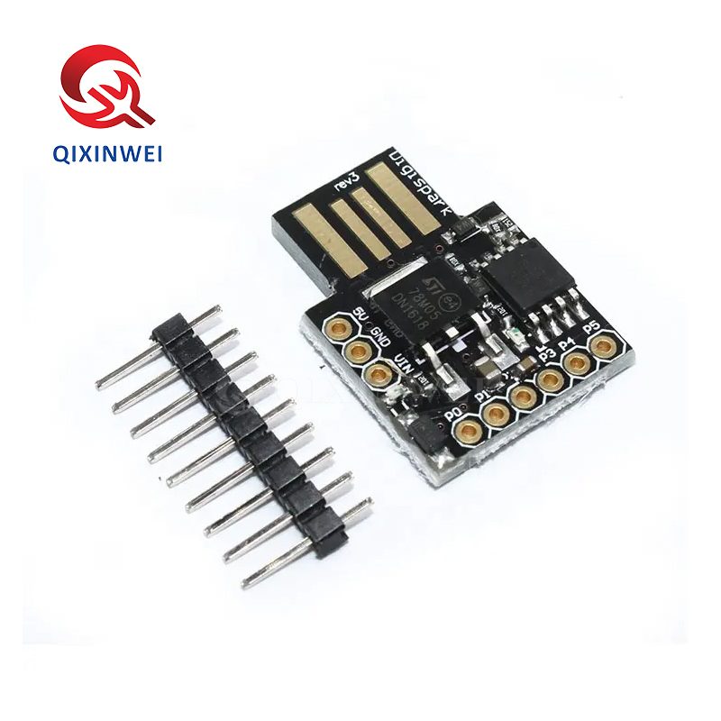
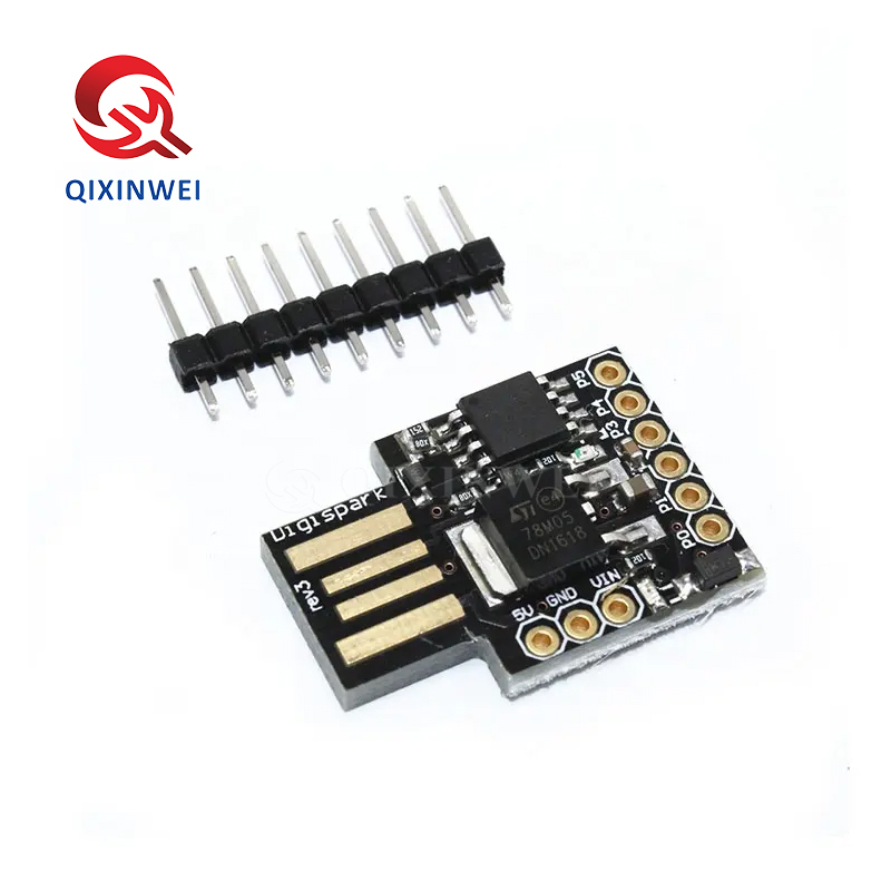
ATTINY85 Micro USB Development Board Module Microcontroller for Smart Toys
ATTINY85 Micro USB Development Board Application features:
◆ Main Chip
ATTINY85 (Atmel/Microchip 8-bit AVR)
◆ Core
AVR RISC architecture
◆ Clock Speed
16.5MHz (built-in PLL)
◆ Memory
Flash: 8KB (~6KB usable, 2KB bootloader)
SRAM: 512 bytes
EEPROM: 512 bytes
◆ Operating Voltage
5V (USB power) or 7-12V (VIN pin)
◆ Digital I/O Pins
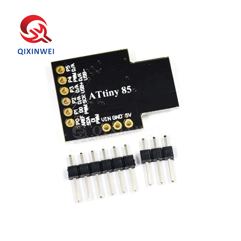
6 pins (P0-P5)
◆ Analog Input Pins
4 pins (10-bit ADC)
◆ PWM Output
2 pins (P0, P1)
◆ Communication Interfaces
USB (built-in, no external chip)
I2C (USI software emulation)
SPI (USI software emulation)
◆ Onboard Resources
Micro USB port (direct download)
Power LED (red)
Reset button
5V regulator (78M05)
3.3V regulator
◆ Programming Methods
Arduino IDE (Digispark board package required)
AVR Studio / Atmel Studio
◆ OS Compatibility
Windows / Mac / Linux
◆ Dimensions
Approx. 27mm × 18mm
◆ Typical Applications
Smart toy control
DIY electronics projects
Small robots
Wearable devices
Sensor data acquisition
RGB LED control (Neopixel)
Keyboard/mouse emulation (HID)
Single-cell battery powered devices
◆ Key Advantages
USB direct download, no programmer needed
Ultra-compact size (thumb-sized)
Arduino IDE compatible, easy to learn
USB HID support (keyboard/mouse emulation)
Low power consumption
Low cost
- Perfect for space-constrained projects
Why Choose QIXINWEI
Years of experience in the electronics industry. Trusted by global customers.
Massive In-Stock Inventory – Ready to ship promptly
BOM Matching Service – One-stop solution, save time
PCBA Customization – Professional engineering team creates tailor-made solutions based on your needs
Cost-Effective & Efficient – Better channel, better cost
A dedicated team makes your procurement smoother.
Contact us for BOM quotes or PCBA inquiries


Quantity(Pieces) | 1 ~ 30000 | 30001 ~ 300000 | > 300000 |
Est. Time(days) | 5 | 7 | To be negotiated |
FAQ:
What is the ATTINY85 micro USB development board and its key specifications?
This is a miniature development board built around the Atmel ATTINY85 microcontroller. It integrates a micro‑USB port and a small number of I/O pins, making it ideal for tiny, low‑cost embedded projects. Key specifications: 8‑bit AVR RISC processor running at up to 16.5 MHz (internal oscillator), 8 KB of Flash program memory, 512 bytes of SRAM, and 512 bytes of EEPROM. It provides 5 general‑purpose I/O pins (some shared with USB), a 10‑bit ADC (4 channels), 2 hardware PWM outputs, and supports USI (Universal Serial Interface) for SPI/I2C. The board can be powered and programmed directly through the micro‑USB port (5 V), and it can emulate a USB device (keyboard, mouse, etc.) using software libraries. It is a popular choice for smart toys, wearables, and simple IoT gadgets.How do I program the ATTINY85 board with the Arduino IDE?
To program the ATTINY85, you must add the ATTinyCore by Spence Konde to the Arduino IDE. Go to File → Preferences, add the board URL, then install “ATTinyCore” from the Boards Manager. After installation, select “ATtiny25/45/85” as the board, choose the processor “ATtiny85”, select the clock speed (typically “16.5 MHz (internal)”), and set the programmer to “USBtinyISP” (if your board has an on‑board bootloader, you can upload directly via USB by selecting the appropriate option). Some clones require an external ISP programmer. After setup, write your sketch and upload. The ATTINY85 has limited memory, so keep sketches small.How does this ATTINY85 board differ from an Arduino Uno or Nano?
The Arduino Uno/Nano use the ATmega328P with 32 KB Flash, 2 KB SRAM, 14 digital I/O, and 6 analog inputs. The ATTINY85 is a much smaller and simpler chip: only 8 KB Flash, 512 bytes SRAM, and 5 I/O pins. The ATTINY85 is ideal for tiny, single‑purpose applications where space and cost are critical, while the Uno/Nano are better for general‑purpose prototyping. The ATTINY85 can also natively emulate USB devices (like a keyboard or mouse) using libraries such as DigiKeyboard, which the ATmega328P cannot do without additional hardware. Choose the ATTINY85 for ultra‑compact projects; choose the Uno/Nano for larger sketches and more I/O.What are the pinout and available I/O on the ATTINY85 micro USB board?
The board typically breaks out 5 I/O pins (often labeled PB0–PB4). PB0, PB1, and PB2 are also used by the USB interface, so they are less available when USB is active. PB3 and PB4 are the safest for general I/O. All pins support software PWM, but hardware PWM is available only on PB0 and PB1. The 10‑bit ADC can be used on any pin, but PB5 (sometimes labeled as Reset) can also be configured as an I/O pin if the Reset function is disabled. The board operates at 5 V logic levels; I/O pins can source up to 40 mA each. For SPI/I2C communication, you must use the software‑based USI library.How do I power the ATTINY85 micro USB board, and what is the power consumption?
The board is powered directly through the micro‑USB port (5 V). It includes an on‑board 3.3 V regulator (on most variants) that can supply a small amount of current to external components. The ATTINY85 is extremely low‑power. In active mode at 16.5 MHz, it draws about 5 mA – 8 mA. It can enter sleep modes that reduce current to as low as ~0.1 µA in power‑down with watchdog disabled. This makes it ideal for battery‑powered smart toys, wearables, and remote sensors. The board can also be powered via the 5V pin if you are not using USB, or directly from a 3.7 V Li‑Po battery connected to the 5V pin (though regulation may be bypassed).Can the ATTINY85 board act as a USB keyboard, mouse, or game controller?
Yes, this is a very popular use case. With libraries like DigiKeyboard or V‑USB, the ATTINY85 can emulate a USB Human Interface Device (HID). It can send keystrokes, mouse movements, or joystick data to a computer. This is commonly used in DIY macro keyboards, password‑entering devices, prank USBs, and game controllers. The sketch must fit within the 8 KB Flash and respect the limited SRAM. Note that the USB emulation uses software bit‑banging, which requires accurate timing and may be less reliable than dedicated USB chips. For reliable operation, use a known‑good DigiKeyboard library and test thoroughly.How much memory does the ATTINY85 have, and what can I fit in it?
The ATTINY85 has 8 KB of Flash (about 6.5 KB – 7 KB usable after the bootloader, if present), 512 bytes of SRAM, and 512 bytes of EEPROM. This is sufficient for small, focused tasks: a USB keyboard emulator, a simple sensor reader, a tiny LED controller, or a basic state machine. You must be very economical with SRAM — avoid large arrays and long strings. For projects that need more memory, consider the ATTINY84 (8 KB Flash, 512 bytes SRAM, but more I/O) or the ATmega328P (32 KB Flash, 2 KB SRAM). The ATTINY85 is perfect for doing one thing very well in the smallest possible footprint.What are the most common problems and how can I troubleshoot them?
1) Board not recognized by computer: install the USB‑to‑serial driver (if required); check the USB cable (must be data‑capable). 2) Upload fails (avrdude error): ensure the correct programmer is selected. Some boards have a bootloader and can be programmed via USB; others require an ISP programmer (like USBtinyISP or an Arduino as ISP). 3) Sketch too large: reduce code size or remove unused libraries; the ATTINY85 has only 8 KB Flash. 4) USB device not working after upload: the USB pins (PB0, PB1, PB2) may conflict with your sketch. Avoid using these pins for I/O when USB is active. 5) Board resets unexpectedly: check the power supply; a noisy USB port or weak cable can cause brown‑out resets.How does the ATTINY85 board handle analog inputs and PWM outputs?
The ATTINY85 features a 10‑bit ADC with up to 4 multiplexed input channels (on PB2, PB3, PB4, and PB5). The analog reference can be the supply voltage (5 V) or the internal 1.1 V bandgap reference. For PWM, hardware PWM is available on PB0 (OC0A) and PB1 (OC0B), while software PWM can be implemented on any pin using libraries like SoftPWM. The hardware PWM provides glitch‑free, high‑frequency signals suitable for LED dimming and motor speed control. The ADC and PWM make the ATTINY85 capable of simple sensor monitoring and actuator control in toys and automation.What are the most typical applications for the ATTINY85 micro USB development board?
Thanks to its tiny size, USB capability, and low power, it is a favourite for smart toys (talking plushies, interactive figurines), USB rubber ducky keystroke injectors, DIY game controllers, LED wearables, miniature IoT sensors, automated button pressers, and educational microcontroller projects. Its ability to run from a small battery and directly communicate with a computer over USB makes it a versatile building block for creative electronics.
- 应用:
- 通用
- 系列:
- ATTINY85
- 特征:
- 标准
- 安装方式:
- 标准
- 尺寸/尺寸:
- 标准
- 描述:
- 标准
- 型号:
- ATTINY85
- 种类:
- 原标准
- 原产地:
- Original
- 品牌:
- Original
- 配置:
- 原标准
- 电流:
- 原标准
- 电压:
- 原标准
- 电压 - 隔离:
- 原标准
- 封装/外壳:
- 原标准
- 相似属性可替代料号:
- 原标准
- 零件号:
- ATTINY85
- Rohs:
- 原件
- 条件:
- 全新和原始
- 类型:
- ATTINY85


