
qixinwei-pcba


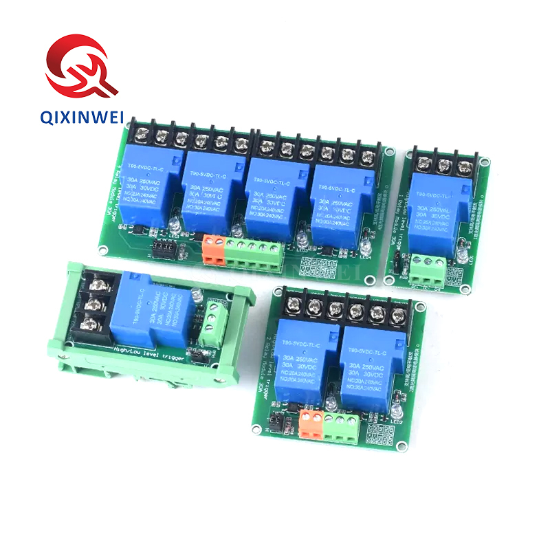
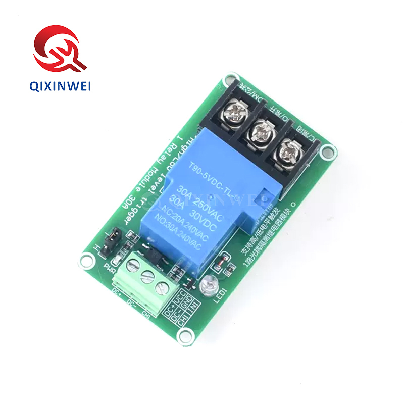
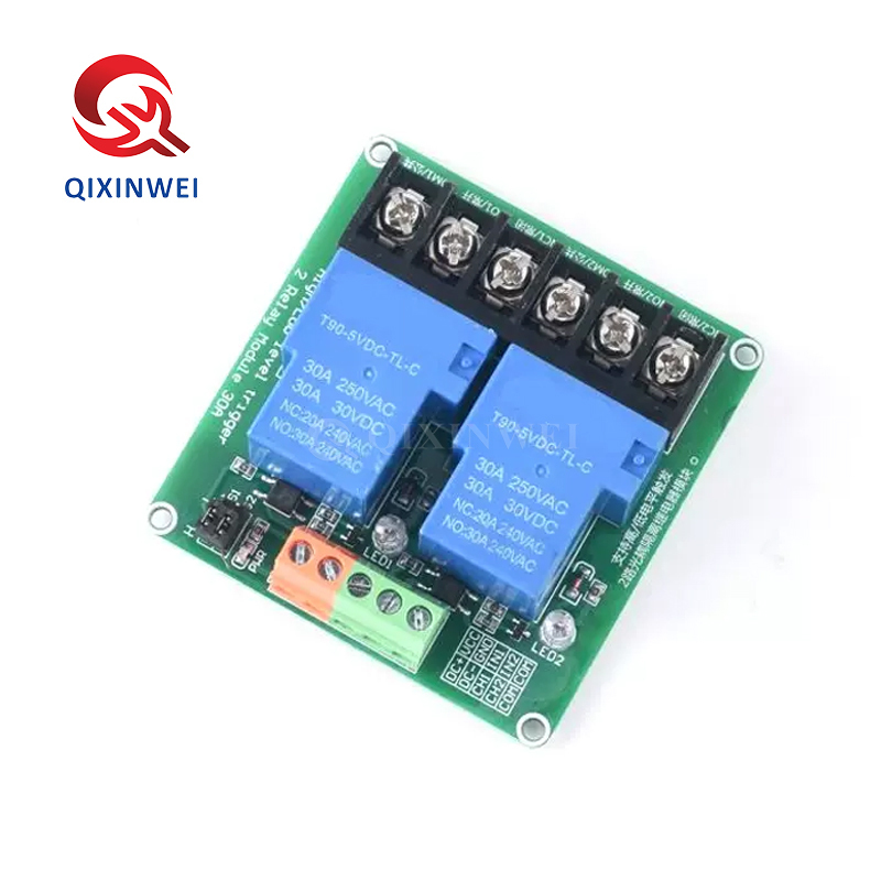
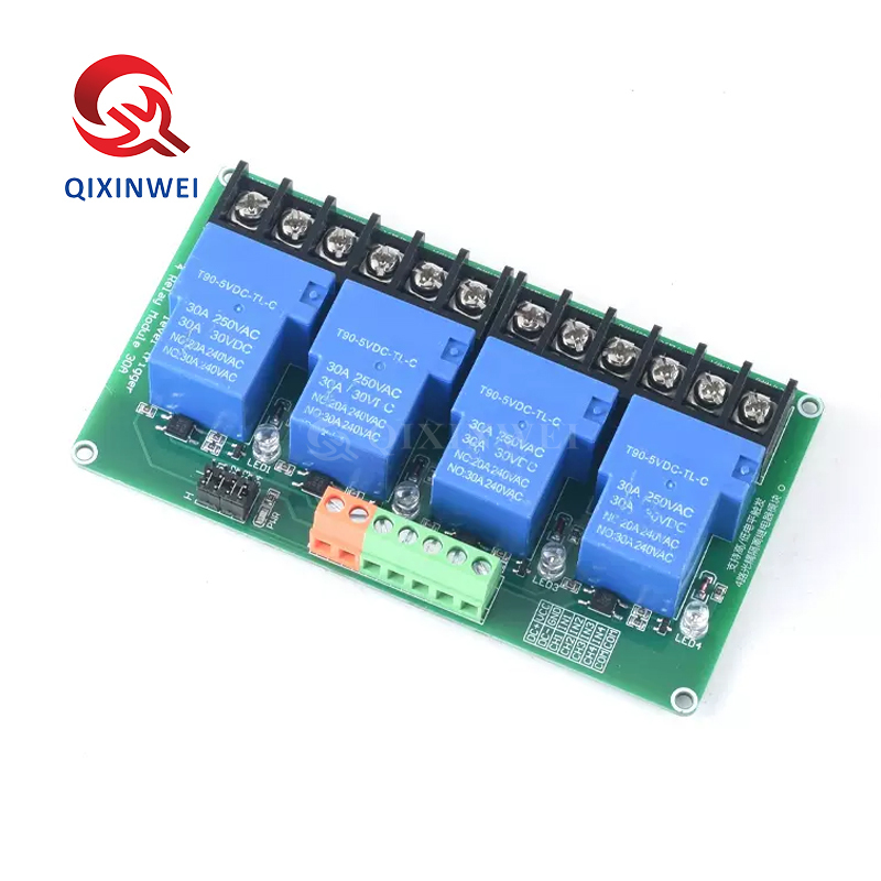
30A Relay Module High Low Level Trigger Optocoupler Isolation for PLC Automation Control
30A Relay Module Application features:
◆ Relay Specifications
Contact capacity: 30A 250V AC / 30A 30V DC
Contact type: 1NO + 1NC (one normally open + one normally closed)
◆ Trigger Method
High level trigger (3V-24V)
Low level trigger (0V-1.5V)
Jumper/shorting cap selectable
◆ Isolation
Optocoupler isolation (PC817 or equivalent) for high/low voltage isolation
◆ Supply Voltage
DC 5V / 12V / 24V (model dependent)
◆ Operating Current
Approx. 50mA-100mA (depends on relay coil)
◆ Input Signal Compatibility
3.3V / 5V / 12V / 24V MCU, PLC, sensor
◆ Onboard Indicators
Power LED (PWR)
Relay activation LED
◆ Pin Definition (Signal Side)
VCC: Power positive
GND: Power ground
IN: Signal input (high/low level)
◆ Pin Definition (Load Side)
COM: Common terminal
NO: Normally open (closed when relay activated)
NC: Normally closed (open when relay activated)
◆ Protection Circuits
Optocoupler isolation
Flyback diode
Transistor driver
◆ Module Dimensions
Approx. 65mm × 35mm × 25mm
30A Relay Module Typical Applications
PLC automation control
Industrial equipment control
High-power appliance switching
Motor start/stop
Smart home control
Water pump control
Heater control
Lighting systems
30A Relay Module Key Advantages
30A high current load capacity
High/low level trigger selectable
Optocoupler isolation for control side protection
Compatible with 3.3V-24V signals
LED indicators for status
- Plug-and-play, easy to integrate
Why Choose QIXINWEI
Years of experience in the electronics industry. Trusted by global customers.
Massive In-Stock Inventory – Ready to ship promptly
BOM Matching Service – One-stop solution, save time
PCBA Customization – Professional engineering team creates tailor-made solutions based on your needs
Cost-Effective & Efficient – Better channel, better cost
A dedicated team makes your procurement smoother.
Contact us for BOM quotes or PCBA inquiries




Quantity(Pieces) | 1 ~ 30000 | 30001 ~ 300000 | > 300000 |
Est. Time(days) | 5 | 7 | To be negotiated |

FAQ:
What is this 30A relay module and its key specifications?
This module combines a high‑power mechanical relay with optocoupler isolation and a selectable high‑/low‑level trigger circuit. It can switch loads up to 30 A at 250 V AC or 30 A at 30 V DC. The relay coil is available in several voltage ratings — common options are 5 V, 12 V, or 24 V DC — and the module provides a separate signal input pin (IN) that accepts a 3.3 V – 24 V logic signal (depending on the specific board). A jumper selects whether the relay activates on a HIGH (active‑high) or LOW (active‑low) level. The on‑board optocoupler (PC817 or similar) provides ~1500 V isolation between the control logic and the relay driver, protecting your microcontroller or PLC from electrical noise and surges. The output side has screw terminals for NO (normally open), COM (common), and NC (normally closed) contacts.How do I select the trigger mode — high‑level or low‑level?
The module has a small jumper cap (or solder bridge) that sets the trigger logic. When set to “HIGH”, the relay energises when the IN pin receives a voltage above ~2.5 V (for a 5 V‑compatible module) — this is ideal when your controller outputs a high signal to turn the load on. When set to “LOW”, the relay energises when the IN pin is pulled to 0 V (GND), which is useful for controllers that start with a high state or for failsafe applications. Always check the silk‑screen or manual; the jumper position is usually marked “H/L”. After changing the jumper, power‑cycle the module for the setting to take effect.How do I connect this relay module to an Arduino, ESP32, or PLC?
Wiring is straightforward. The module typically has four control pins: DC+ (relay coil power), DC‑ (coil ground), IN (trigger signal), and sometimes a separate VCC/GND for the optocoupler input (often jumpered with DC+). Connect DC+ and DC‑ to a power supply matching the relay coil voltage (e.g., 5 V, 12 V, or 24 V). Connect IN to a digital output pin of your microcontroller or PLC. Do not connect the relay coil power to the microcontroller’s 5 V pin unless it can supply enough current (~70 mA per relay). The relay output terminals (NO, COM, NC) are completely isolated — wire your load in series with the appropriate contacts. The jumper for trigger level must be set before wiring the signal pin.What are the maximum switching voltage and current ratings?
The relay contacts are rated for 30 A at 250 V AC (resistive load) and 30 A at 30 V DC. For inductive loads (motors, solenoids, transformers), the current must be de‑rated to about 30 % – 50 % of the resistive rating because the inrush and arc can weld the contacts. Always add a snubber circuit or flyback diode across the load to protect the contacts. The relay’s mechanical life is typically > 10 million operations, and electrical life at full load is about 100,000 cycles. Exceeding the ratings will destroy the relay and can create a fire hazard.What is the purpose of the optocoupler isolation on this module?
The on‑board optocoupler (photocoupler) creates a galvanic barrier between the low‑voltage control side (IN pin) and the relay driver circuit. This prevents ground loops, electrical noise, and voltage spikes from the load side from travelling back into your microcontroller or PLC. The isolation voltage is typically 1,500 V – 2,500 V. It also means that the IN pin is fully floating — it does not share a ground with the relay coil supply unless you bridge them with an external connection. This makes the module extremely safe for industrial automation where high‑power AC devices are being controlled.What power supply does the relay module need, and how do I match the coil voltage?
The relay coil voltage is fixed by the specific module you purchased — common values are 5 V, 12 V, or 24 V DC. You must power the DC+ and DC‑ terminals with the correct voltage; using a higher voltage will burn the coil. The IN signal can often be a lower voltage (e.g., 3.3 V from an ESP32) even if the coil uses 12 V, because the optocoupler’s LED only needs a few milliamps. However, the coil supply and the signal supply must share a common ground if the jumper configuration ties them together (check the board’s schematic). For battery‑powered projects, a 12 V module can be run from a 3S Li‑Ion pack; a 5 V module from a USB power bank.Can this relay module switch DC loads? What about inductive loads like motors?
Yes, it can switch DC up to 30 A at 30 V. However, DC arcing is more severe than AC, so do not push the maximum ratings continuously. For inductive DC loads (motors, solenoids), you must place a flyback diode directly across the load (cathode to positive) to absorb the voltage spike when the relay opens; otherwise, the arc can quickly destroy the contacts. For AC inductive loads, a snubber (RC) network or MOV is recommended. The module itself does not include any load‑side protection; you must add it externally.How fast can this relay switch? Is it suitable for PWM or high‑speed control?
This is a mechanical relay, not a solid‑state switch. The operating time is typically 5 ms – 10 ms to close, and the release time is similar. It is not suitable for PWM or high‑frequency switching — trying to do so will cause the relay to overheat and fail within seconds. The maximum switching frequency for this relay is about 1–2 operations per second at full load, and much less for long life. If you need fast, silent switching, use a MOSFET module or solid‑state relay (SSR).Why does my relay module not switch, or why does it chatter?
Common causes: 1) Wrong trigger level jumper – check that the H/L jumper matches your control signal. 2) Insufficient coil power – the supply for DC+/DC‑ must be able to deliver enough current (a 12 V relay coil draws about 30 mA – 40 mA; a 5 V coil draws ~70 mA). A weak USB port or GPIO pin cannot power the coil directly. 3) Signal voltage too low – if using a 3.3 V controller with a 5 V module, the optocoupler LED may not turn on fully; check the module’s signal input range. 4) No common ground – if the IN signal is not referenced to the module’s ground, the optocoupler cannot conduct. 5) Relay contacts welded – if switching a high inductive load without a snubber, the contacts may have welded. Tap the relay lightly to test; if it frees, add external protection.What are the most typical applications for this 30A optocoupler relay module?
It is a workhorse in PLC industrial control panels, home automation (heavy lighting, water heaters), pump and motor starters, greenhouse irrigation controllers, HVAC control, CNC machine power switching, and power supply automatic transfer switches. Its high current rating, isolated trigger, and flexible trigger logic make it easy to interface with any microcontroller or PLC that needs to safely switch high‑power AC or DC loads.
- 原产地:
- Original
- 品牌:
- Original
- 型号:
- Relay module 30A
- 种类:
- 继电器模块
- 芯片组:
- 继电器模块30A
- 应用:
- 通用


