Electronic components
Resistors, Capacitors and RC Filters: A Practical Guide to Principles, Selection, Testing and Circuit Design
Resistors, capacitors and filters are some of the most basic components in electronic circuits, but they play very different roles in circuit design. A resistor is mainly used for current limiting, voltage division, biasing and load control. A capacitor can store electrical energy, block DC, couple AC signals, suppress noise and stabilize power rails. When resistors and capacitors are combined, they can form RC filters that selectively pass or attenuate different frequency components.
For engineers working on power supplies, industrial control systems, embedded devices, IoT equipment, sensors, audio equipment and communication products, understanding the relationship between resistance, capacitance and frequency response is essential. Correct component selection also requires more than checking the nominal value. Power rating, voltage rating, tolerance, ESR, leakage current, temperature characteristics, package and supply availability can all affect the final design.
This article explains the fundamental differences between resistors and capacitors, how RC low-pass and high-pass filters work, how to calculate the cutoff frequency, how to select components, and how to troubleshoot common problems in practical circuits.
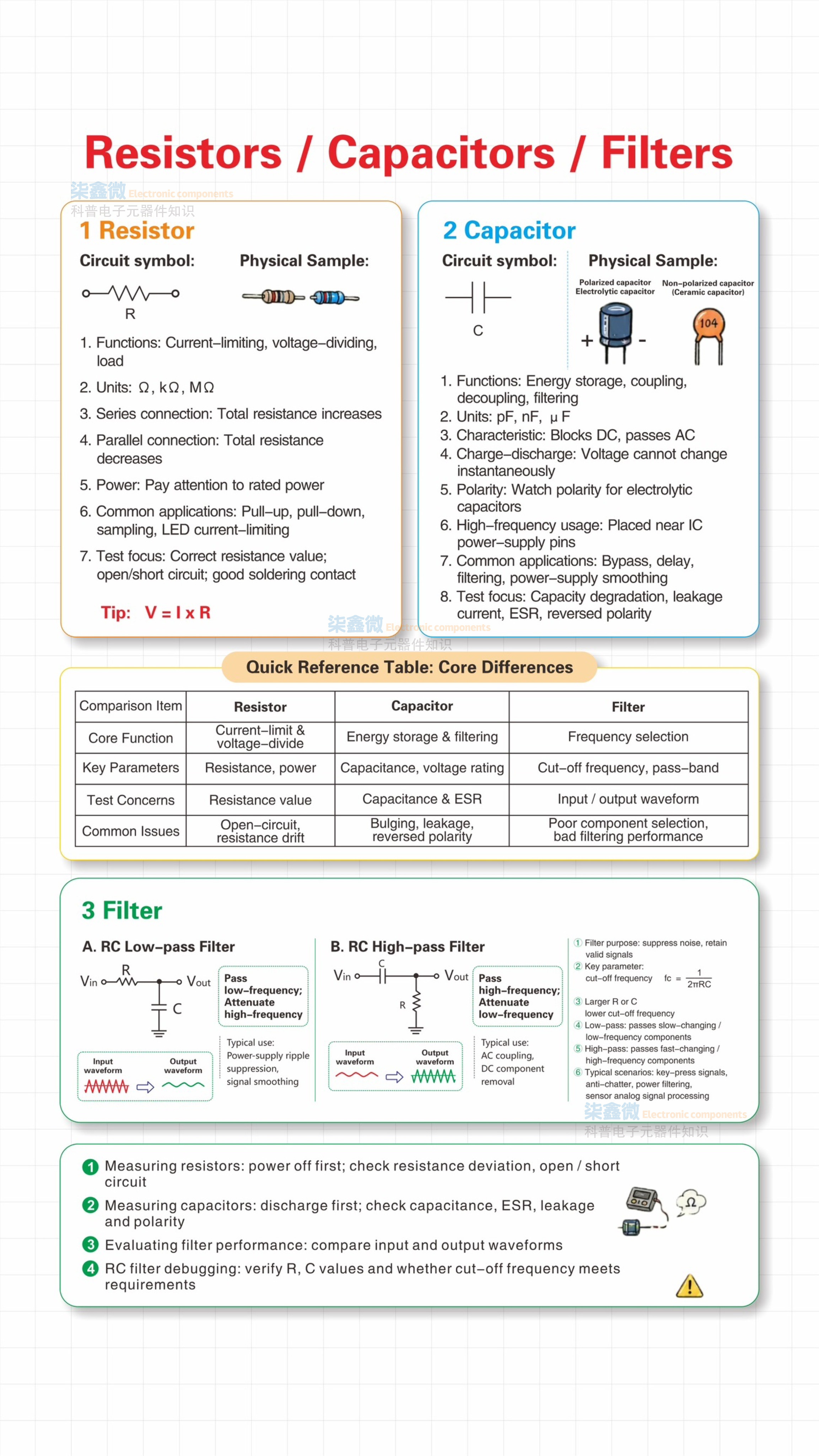
1. What Is a Resistor?
A resistor is a passive electronic component that limits or controls current in a circuit. Its basic electrical relationship is described by Ohm's law:
V = I × R
V represents voltage, I represents current, and R represents resistance.
In practical electronic circuits, resistors are used for current limiting, voltage division, signal conditioning, transistor biasing, pull-up and pull-down circuits, feedback networks, load simulation and termination.
The resistance unit is the ohm (Ω). Common values include Ω, kΩ and MΩ. For example, 1 kΩ equals 1,000 Ω, while 1 MΩ equals 1,000,000 Ω.
Resistors in series
When resistors are connected in series, their total resistance is the sum of the individual resistance values:
Rtotal = R1 + R2 + R3 + ...
The same current flows through each resistor, while the total voltage is divided according to the resistance of each component.
Series resistors are commonly used for current limiting and voltage divider circuits.
Resistors in parallel
For resistors connected in parallel, the equivalent resistance is calculated as:
1/Rtotal = 1/R1 + 1/R2 + 1/R3 + ...
The total resistance of a parallel network is lower than the smallest individual resistance.
Parallel resistor networks are useful when a specific resistance value is required or when power dissipation needs to be distributed between multiple components.
2. Resistor Selection Is Not Only About Resistance
A common mistake during component selection is to focus only on the resistance value.
For example, a circuit may require a 100 Ω resistor, but not every 100 Ω resistor is suitable. The engineer also needs to consider tolerance, rated power, maximum working voltage, temperature coefficient, package size and pulse capability.
Power dissipation is particularly important.
The basic power relationships are:
P = V × I
P = I² × R
P = V² / R
If the actual power exceeds the resistor's rated power, the component may overheat, change resistance or eventually fail.
For this reason, resistor selection should consider both the required resistance and the actual electrical conditions of the circuit.
3. What Is a Capacitor?
A capacitor is a passive component that stores electrical energy in an electric field. Unlike a resistor, its electrical behavior is strongly related to frequency.
The basic charge relationship is:
Q = C × V
Q represents electrical charge, C represents capacitance and V represents voltage.
Capacitance is measured in farads (F), although practical electronic circuits commonly use pF, nF and μF.
Capacitors are widely used for power-supply decoupling, filtering, energy storage, signal coupling, timing circuits, transient suppression and voltage stabilization.
The most important characteristic of a capacitor in filtering applications is that its impedance decreases as frequency increases.
The ideal capacitive reactance is:
Xc = 1 / (2πfC)
As frequency increases, capacitive reactance decreases. This frequency-dependent characteristic is the reason capacitors are so useful in filtering circuits.
4. Polarized and Non-Polarized Capacitors
Capacitors can generally be divided into polarized and non-polarized types.
Electrolytic capacitors are typically polarized. Their positive and negative terminals must be connected correctly according to the circuit requirements. Reverse polarity can result in excessive leakage, overheating or component failure.
Ceramic capacitors and many film capacitors are generally non-polarized and can be installed in either direction.
When replacing a capacitor, engineers should therefore check not only the capacitance value but also the polarity, voltage rating and capacitor technology.
For example, replacing a 10 μF capacitor with another 10 μF capacitor does not automatically guarantee equivalent circuit performance. ESR, leakage current, temperature characteristics and voltage rating may all be different.
5. What Parameters Should Be Considered When Selecting a Capacitor?
Capacitance is only one of the important specifications.
A practical capacitor selection should consider:
Capacitance value, voltage rating, tolerance, ESR, leakage current, temperature range, dielectric characteristics, frequency characteristics and package size.
For power-supply applications, ESR can have a significant influence on ripple voltage, transient response and thermal performance.
For high-frequency decoupling, the actual impedance of the capacitor at the operating frequency is more important than simply looking at the nominal capacitance value.
This is why two capacitors with the same nominal capacitance can perform differently in the same circuit.
6. What Is an RC Filter?
An RC filter is a frequency-selective circuit consisting primarily of a resistor and capacitor.
The resistor and capacitor work together to determine which frequency components are passed and which are attenuated.
The basic cutoff-frequency formula for a first-order RC filter is:
fc = 1 / (2πRC)
where:
fc is the cutoff frequency in hertz,
R is the resistance in ohms,
C is the capacitance in farads.
The cutoff frequency is commonly defined as the point where the output amplitude has fallen to approximately 70.7% of the passband amplitude, corresponding to approximately -3 dB.
The formula is simple, but real-world filter performance also depends on source impedance, load impedance, component tolerance and parasitic effects.
7. How Does an RC Low-Pass Filter Work?
An RC low-pass filter allows lower-frequency signals to pass while attenuating higher-frequency components.
The typical configuration places a resistor in series with the input signal and a capacitor from the output node to ground. The output voltage is taken across the capacitor.
At low frequencies, the capacitor has relatively high impedance, so most of the input signal appears at the output.
As frequency increases, the capacitor's impedance decreases. More of the high-frequency signal is therefore diverted through the capacitor toward ground, reducing the high-frequency component at the output.
This makes RC low-pass filters useful for:
Power-supply noise reduction, sensor signal conditioning, PWM smoothing, ADC input filtering, analog signal processing and control-system noise suppression.
For example, a noisy sensor output may contain a useful low-frequency signal together with high-frequency interference. An appropriately designed RC low-pass filter can reduce the unwanted high-frequency component before the signal enters an ADC or microcontroller.
However, a first-order RC low-pass filter does not completely block frequencies above the cutoff frequency. Its attenuation increases gradually with frequency, with an ideal slope of approximately 20 dB per decade beyond the cutoff region.
8. How Does an RC High-Pass Filter Work?
An RC high-pass filter has the opposite frequency response.
The capacitor is connected in series with the input signal, while the resistor is connected from the output node to ground. The output is taken across the resistor.
At DC and very low frequencies, the capacitor presents high impedance, so the signal is strongly attenuated.
As the frequency increases, the capacitor's impedance decreases and more of the AC signal reaches the output.
The same cutoff-frequency equation applies:
fc = 1 / (2πRC)
RC high-pass filters are commonly used for AC coupling, DC blocking, removal of low-frequency drift, audio signal conditioning and pulse or transient detection.
The key difference between the two configurations is therefore the frequency range they are designed to pass.
An RC low-pass filter passes low frequencies and attenuates high frequencies.
An RC high-pass filter passes high frequencies and attenuates low frequencies.
9. How to Calculate an RC Filter
Suppose a circuit requires an RC low-pass filter with a cutoff frequency of approximately 1 kHz.
If we select:
R = 10 kΩ
Then the required capacitance can be calculated as:
C = 1 / (2πRfc)
The result is approximately:
C = 15.9 nF
A practical standard capacitor value can then be selected based on the required tolerance, voltage rating and actual circuit conditions.
Alternatively, if the designer prefers to use a 100 nF capacitor, the resistance can be adjusted to approximately:
R = 1.59 kΩ
This demonstrates an important principle in RC filter design: there are usually multiple combinations of R and C that can produce approximately the same cutoff frequency.
However, these combinations are not necessarily equivalent in a real circuit.
A very large resistor may increase sensitivity to leakage currents and external interference, while a very small resistor may increase current consumption and load the preceding circuit.
10. The Relationship Between RC Time Constant and Filtering
Another important concept is the RC time constant:
τ = R × C
The time constant describes how quickly a capacitor charges or discharges through a resistor.
For a first-order RC circuit:
fc = 1 / (2πτ)
This relationship connects the time-domain and frequency-domain behavior of an RC network.
A larger RC time constant results in slower charging and discharging and a lower cutoff frequency.
A smaller RC time constant results in faster charging and discharging and a higher cutoff frequency.
This is why RC circuits are used not only for filtering but also for timing, pulse shaping, power-on delay and transient control.
11. How to Choose the Correct R and C Values
Selecting R and C values should not be based only on the cutoff-frequency equation.
The first step is to determine the actual signal requirement.
If the circuit is filtering sensor noise, determine the frequency range of the useful sensor signal and the approximate frequency range of the noise.
If the circuit is filtering a power rail, determine whether the objective is to suppress switching noise, ripple, transient spikes or low-frequency fluctuations.
After identifying the target frequency range, the designer should evaluate the following factors.
Source impedance
The output impedance of the preceding circuit becomes part of the actual filter network.
If the source impedance is relatively high, it can change the effective resistance and therefore shift the cutoff frequency.
Load impedance
The load connected to the filter output can also affect the filter.
A low-impedance load may change the effective resistance of the RC network, resulting in a different cutoff frequency and attenuation than the theoretical calculation suggests.
Component tolerance
Real resistors and capacitors are not ideal.
For example, if a capacitor has a ±10% tolerance, the actual capacitance may differ significantly from its nominal value. Since cutoff frequency depends on both R and C, the actual filter frequency will also vary.
Temperature characteristics
Resistance and capacitance can change with temperature.
This is especially important in industrial equipment, automotive electronics, outdoor devices and other products that operate across a wide temperature range.
PCB parasitic effects
At higher frequencies, PCB traces, component leads, device pins and surrounding conductors can introduce additional capacitance and inductance.
As the operating frequency increases, these parasitic parameters can become significant enough to change the actual filter response.
12. Why Does the Actual RC Filter Differ From the Calculation?
It is common for an engineer to calculate an RC filter theoretically and then measure a different cutoff frequency on the actual PCB.
This does not necessarily mean that the formula is wrong.
The simplified equation assumes ideal components and simplified source and load conditions.
In a real circuit, several factors can affect the result.
The source may have a non-zero output impedance. The load may be lower than expected. The capacitor may have tolerance or DC-bias-related capacitance changes. ESR and ESL may affect its high-frequency impedance. PCB parasitic capacitance may also influence the circuit.
Measurement equipment can introduce additional loading as well.
Therefore, when the measured response differs from the theoretical response, engineers should examine the complete signal path rather than immediately replacing the resistor or capacitor.
13. How to Test a Resistor Correctly
Resistance measurement appears simple, but testing a resistor directly on a PCB can sometimes produce misleading results.
Other components connected in parallel may cause the measured resistance to appear lower than the resistor's actual value.
The recommended troubleshooting process is to first disconnect the power supply and safely discharge relevant capacitors. Then check whether the resistor is connected to other circuit paths that could affect the measurement.
If the measured resistance is significantly different from the nominal value, the resistor should be evaluated together with its tolerance, operating temperature and circuit conditions.
An open resistor may indicate excessive power dissipation, overheating, mechanical damage or another fault in the circuit.
A resistor that has drifted significantly from its original value may also indicate long-term thermal or electrical stress.
14. How to Test a Capacitor Correctly
Capacitor testing requires more than checking capacitance.
A capacitor can measure close to its nominal capacitance and still have excessive ESR or leakage current.
This is especially common in aging power-supply circuits.
For example, an electrolytic capacitor may still show a relatively normal capacitance value while its ESR has increased significantly. In this situation, the capacitor may no longer provide effective filtering, resulting in increased ripple, unstable voltage or abnormal heating.
When testing a capacitor, engineers should consider capacitance, ESR, leakage current, polarity, voltage rating and physical condition.
For polarized capacitors, polarity must be checked carefully.
For power circuits, capacitors should also be discharged safely before measurement.
15. Common RC Filter Design Mistakes
One of the most common mistakes is selecting R and C values only according to the theoretical cutoff frequency.
A second common mistake is ignoring the load impedance. A filter designed with a high-impedance load in mind may perform very differently when connected to a low-impedance input.
Another mistake is using an unsuitable capacitor type. A capacitor with the correct nominal capacitance may still have inappropriate ESR, temperature characteristics or voltage rating.
Engineers should also avoid placing sensitive filter circuits too close to noisy switching nodes without considering PCB layout.
For high-frequency applications, the physical layout can become just as important as the schematic.
16. RC Filter vs. LC Filter
RC filters are simple, low-cost and easy to implement, but they are not suitable for every filtering requirement.
A first-order RC filter provides relatively gradual attenuation. If the application requires stronger frequency selectivity or lower insertion loss, an LC filter may be more appropriate.
RC filters also introduce voltage drop because of the series resistance. This can be acceptable for low-current signal circuits but problematic for high-current power applications.
LC filters are therefore commonly considered when higher current capability, stronger filtering or lower DC loss is required.
Active filters can provide additional control over gain and frequency response and may be preferred when a more precise frequency response is required.
The correct filter type depends on the application rather than simply the availability of resistor and capacitor components.
17. Resistor and Capacitor Selection for Production
Prototype development and mass production have different component requirements.
During the prototype stage, an engineer may only need to confirm whether a circuit works with a particular resistor or capacitor.
During mass production, additional factors become important, including stable supply, manufacturer consistency, lifecycle status, package availability, alternative parts and long-term BOM risk.
This is especially important for electronic products with long production cycles.
A component that is technically suitable but difficult to source consistently can become a production risk.
For engineering teams that need support with electronic component sourcing, QIXINWEI provides services including BOM matching, component sourcing, parameter comparison, sample procurement and replacement evaluation. The goal is to help customers evaluate components from both an engineering and supply-chain perspective, rather than simply providing a part number.
For resistor, capacitor, power component, IC and other electronic component requirements, QIXINWEI can also assist with comparing specifications and identifying practical sourcing options according to the project requirements.
18. Practical Checklist for Engineers
When selecting a resistor, check the resistance value, tolerance, rated power, maximum voltage, temperature coefficient, package and pulse capability.
When selecting a capacitor, check capacitance, voltage rating, tolerance, ESR, leakage current, dielectric characteristics, temperature range, frequency behavior and package.
When designing an RC filter, check the target cutoff frequency, source impedance, load impedance, signal amplitude, component tolerance and PCB layout.
When preparing a production BOM, also check manufacturer, lifecycle status, supply stability, package compatibility and potential replacement options.
This approach can significantly reduce the risk of selecting a component that looks correct on paper but performs poorly or becomes difficult to source during production.
Frequently Asked Questions About Resistors, Capacitors and RC Filters
What is the main difference between a resistor and a capacitor?
A resistor primarily limits current and dissipates electrical energy, while a capacitor stores electrical energy and has frequency-dependent impedance. This makes capacitors particularly useful for filtering, coupling and decoupling.
What does a resistor do in an RC filter?
The resistor works with the capacitor to determine the time constant and cutoff frequency. It also controls current and affects the interaction between the filter and the source or load.
What does a capacitor do in an RC filter?
The capacitor provides frequency-dependent impedance. Depending on the circuit configuration, it can attenuate high-frequency signals or block low-frequency and DC components.
What is the formula for an RC filter cutoff frequency?
The basic formula for a first-order RC filter is:
fc = 1 / (2πRC)
The cutoff frequency is determined by both resistance and capacitance.
What happens when the resistance increases?
If capacitance remains unchanged, increasing resistance increases the RC time constant and lowers the cutoff frequency.
What happens when capacitance increases?
If resistance remains unchanged, increasing capacitance also increases the RC time constant and lowers the cutoff frequency.
Is the cutoff frequency the point where the signal is completely blocked?
No. The cutoff frequency is normally defined as the -3 dB point. A first-order RC filter continues to attenuate the signal progressively above or below the cutoff frequency depending on the filter configuration.
What is the difference between an RC low-pass and high-pass filter?
An RC low-pass filter passes lower frequencies and attenuates higher frequencies. An RC high-pass filter blocks DC and lower frequencies while allowing higher-frequency signals to pass.
Why does my RC filter have a different cutoff frequency from the calculated value?
The difference may result from source impedance, load impedance, component tolerance, capacitor characteristics, parasitic capacitance, PCB layout or measurement loading.
Does capacitor ESR matter?
Yes. ESR can affect the actual impedance and filtering performance of a capacitor, particularly in power-supply and higher-frequency applications.
Can I replace a capacitor with another capacitor having the same capacitance?
Not automatically. Voltage rating, ESR, leakage current, dielectric type, tolerance, temperature characteristics and package should also be considered.
Can different R and C combinations produce the same cutoff frequency?
Yes. Different R and C combinations can have the same RC product and therefore approximately the same theoretical cutoff frequency. However, their real-world behavior may differ because of source impedance, load impedance, leakage, noise sensitivity and power consumption.
When should an RC filter be replaced by an LC filter?
An LC filter may be preferable when stronger filtering, higher current capability or lower DC power loss is required. The appropriate choice depends on the application and operating conditions.
Can an RC filter be used for power-supply noise?
Yes. RC filters can be effective for reducing noise and ripple in relatively low-current power or signal circuits. For high-current power applications, designers should carefully evaluate voltage drop and power dissipation and may need an LC or other filtering solution.
Conclusion
Resistors, capacitors and RC filters are fundamental components, but their practical applications involve much more than their basic circuit symbols.
A resistor controls current, voltage and power. A capacitor stores charge and responds differently to different frequencies. By combining the two, engineers can create simple and effective low-pass and high-pass filters for signal conditioning, noise reduction, timing and power management.
The most important RC filter equation is:
fc = 1 / (2πRC)
However, calculating the cutoff frequency is only the beginning. A reliable circuit design must also consider source impedance, load impedance, component tolerance, capacitor ESR, leakage current, temperature characteristics, parasitic effects and PCB layout.
For prototype development and mass production, component availability and supply stability are equally important. QIXINWEI supports electronic component sourcing, BOM matching, parameter comparison, sample procurement and replacement evaluation, helping engineering and purchasing teams find suitable components while balancing technical requirements and supply-chain considerations.
Whether the project requires resistors, capacitors, filters, power components, ICs or other electronic components, the right approach is to evaluate the component based on the complete application rather than selecting a part number only from its nominal value.
0users like this.