
Arduino & Embedded Electronics Starter Kits | IoT DIY Learning Modules
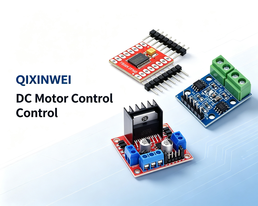
DC Motor Control Module: Complete Guide to Motor Drivers — Popular Modules (L298N, L9110S, TB6612)
What Is a DC Motor Control Module?
Introduction to DC Motor Control Module
How Does a DC Motor Control Module Work?
Understanding how a motor driver works is essential for using it correctly. Let’s break it down.
The Core Components
A modern DC motor controller typically consists of several key elements:
Power Supply Module — delivers the required current and voltage to the motor, ensuring stable power delivery even during load changes
PWM Controller — regulates motor speed by varying the duty cycle of pulses sent to the motor
H-Bridge Circuit — enables bidirectional motion (forward and reverse)
Current Control Circuit — protects against excessive current that could damage the driver or motor
Logic Control Unit — processes input from the microcontroller and translates it into control signals
The H-Bridge Principle
The most important concept in DC motor control is the H-bridge. An H-bridge is a circuit with four transistor switches arranged in an H shape around the motor. By closing different pairs of switches, you can control the direction of current flow through the motor:
PWM Speed Control
Speed control is achieved using Pulse Width Modulation (PWM) . Instead of varying the supply voltage directly, the controller rapidly switches the motor power on and off. By adjusting the ratio of “on” time to “off” time — known as the duty cycle — the controller controls the effective voltage applied to the motor:
100% duty cycle = motor runs at full speed
0% duty cycle = motor is stopped
PWM control offers several advantages: high efficiency, minimal power loss, precise speed control, and reduced heat generation compared to linear control methods.
Types of DC Motor Controllers
DC motor controllers come in several varieties, each suited to different applications:
1. Brushed DC Motor Controllers
Designed for traditional brushed DC motors. They are generally simpler, less expensive, and commonly found in toys, small appliances, and basic automation systems.
2. Brushless DC (BLDC) Motor Controllers
BLDC motors lack brushes and commutators, so their controllers are more complex and must manage electronic commutation. These are found in high-performance or noise-sensitive applications like drones, electric vehicles, and computer cooling fans.
3. Stepper Motor Drivers
Control stepper motors by sending pulses to the motor windings. These are heavily used in 3D printers and CNC machines.
4. Open-Loop vs Closed-Loop Controllers
Open-loop controllers regulate speed based on a fixed PWM command without feedback
Closed-loop controllers use feedback from encoders or tachometers to regulate speed or torque more accurately
Key Parameters to Consider When Choosing a Motor Driver
Selecting the right motor driver module for your project requires understanding these critical specifications:
1. Motor Supply Voltage Range
The driver must support your motor’s operating voltage. Common ranges include:
2. Continuous Output Current
The maximum current the driver can deliver continuously. Choose a driver rated above your motor’s current draw:
3. Peak Current Rating
The maximum current the driver can handle for short bursts (e.g., during motor startup). This is typically higher than the continuous rating:
4. Logic Voltage Level
Ensure the driver is compatible with your microcontroller’s logic level (3.3V or 5V). Most modern drivers support both.
5. PWM Frequency Support
Higher PWM frequencies allow smoother motor control but require faster drivers. For example, TB6612FNG supports up to 100kHz PWM, while L298N is limited to about 25kHz.
6. Efficiency
Higher efficiency means less power wasted as heat. MOSFET-based drivers like TB6612FNG achieve up to 94% efficiency, while bipolar drivers like L298N typically achieve only 45–65%.
7. Protection Features
Look for built-in protection against overcurrent, overvoltage, overheating, and short circuits.
Popular DC Motor Driver Modules Compared
Here’s a side-by-side comparison of the most popular motor driver modules for makers:
| Feature | L9110S | L298N | TB6612FNG |
|---|---|---|---|
| Motor Supply Voltage | 2.5–12V | 5–46V | 2.5–13.5V |
| Continuous Current | 0.8A/ch | 2A/ch | 1.2A/ch |
| Peak Current | ~1.5A | 4A | 3.2A |
| PWM Frequency | ≤10kHz | ≤25kHz | ≤100kHz |
| Standby Current | 0.1mA | 6mA | 0.5µA |
| Typical Efficiency | ~65% | ~45% | ~94% |
| Best For | Tiny robots, low-cost projects | Education, prototyping, high voltage | High-performance, battery-powered projects |
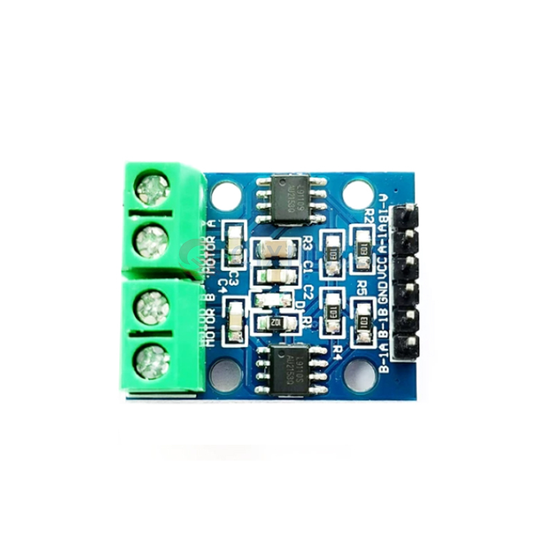
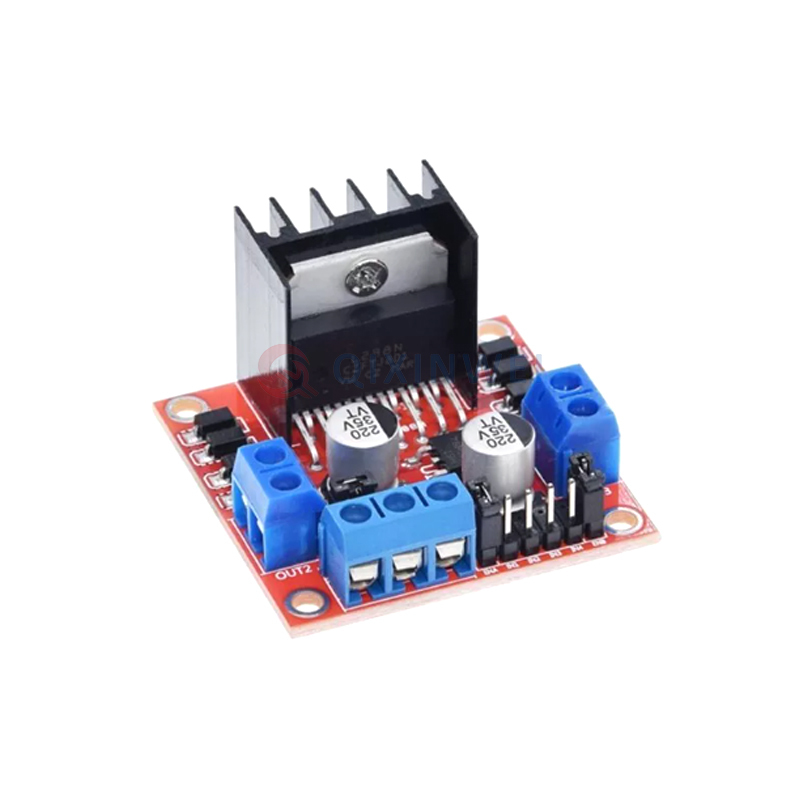
L298N — The most popular motor driver in the Arduino ecosystem. It’s based on the ST L298N dual full H-bridge driver IC and has been the go-to choice for makers for over a decade. Pros: Handles high voltage (up to 46V) and high current (2A continuous). Cons: Uses bipolar transistors internally, causing a 2–3V voltage drop that wastes significant power as heat. Efficiency drops to around 60–70%.
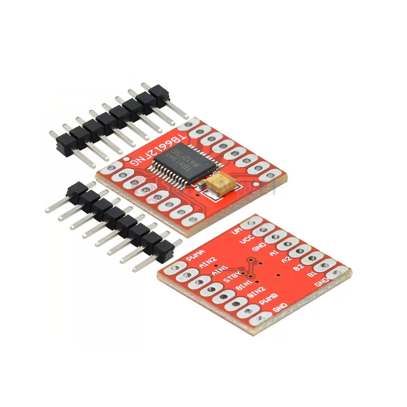
TB6612FNG — A modern MOSFET-based driver offering much higher efficiency (up to 94%). Pros: Very low standby current (0.5µA), supports high PWM frequencies (100kHz), compact. Cons: Lower maximum voltage (13.5V) and current (1.2A) than L298N.
L9110S — A compact, ultra-budget dual-channel driver ideal for small robots and toy-grade motors. Pros: Very cheap, simple to use, works at low voltages (2.5V+). Cons: Limited to 0.8A continuous current.
What Is a DC Motor Control Module Used For?
DC motor control modules are used wherever precise motor control is needed. Here are the most common applications:
1. Robotics
From simple line-following robots to complex humanoid robots, motor drivers control the wheels, arms, and joints.
2. Electric Vehicles and Drones
Motor controllers are essential in e-bikes, scooters, and drones, where they manage motor speed, direction, and torque.
3. 3D Printers and CNC Machines
Stepper motor drivers control the precise movements of print heads and cutting tools.
4. Conveyor Belts and Material Handling
In industrial automation, motor controllers manage the speed and direction of conveyor systems.
5. Home Appliances
From washing machines to vacuum cleaners, motor drivers control the motors that power these devices.
6. Automotive Subsystems
Power windows, seat adjusters, and cooling fans all use DC motor controllers.
7. DIY Projects
Arduino and ESP32 projects like robotic arms, automated plant watering systems, and remote-controlled cars all rely on motor drivers.
FAQs:
A DC motor control module is a professional drive board used to control DC motor operation. It mainly realizes precise PWM speed regulation, forward/reverse rotation switching, start-stop control and braking, widely used in robots, industrial automation devices, DIY electronics and smart home equipment.
Yes. Most standard DC motor control modules support 3.3V and 5V logic signals, which are fully compatible with Arduino, Raspberry Pi, STM32 and other mainstream microcontroller boards, with simple wiring and convenient secondary development.
Most universal DC motor control modules feature a wide voltage design, supporting 6V to 60V DC input. It covers low-voltage small motors for DIY projects and medium-high voltage industrial DC motors to meet diverse usage needs.
Q4: What is PWM speed control?
PWM (Pulse Width Modulation) controls motor speed by rapidly switching the power on and off. The ratio of “on” time to “off” time (the duty cycle) determines the average voltage and thus the motor speed.
Q5: What’s the difference between L298N, L9110S, and TB6612FNG?
L298N is a classic driver handling high voltage (5–46V) and current (2A), but it’s inefficient (~45%). L9110S is a compact, cheap driver for small motors (0.8A, 2.5–12V). TB6612FNG is a modern, highly efficient MOSFET driver (94% efficiency) with low standby current.
Q6: How do I control motor speed with PWM?
Most motor driver modules have dedicated PWM input pins. By sending a PWM signal from your microcontroller to these pins, you can control the motor speed. The higher the duty cycle, the faster the motor runs.
Q7: What protection features should I look for?
Look for overcurrent protection, overvoltage protection, thermal shutdown, and short-circuit protection. These features protect both the driver and the motor from damage.
Q8: Can I use a motor driver with both 3.3V and 5V microcontrollers?
Most modern motor drivers support both 3.3V and 5V logic levels. Always check the datasheet to confirm compatibility.
Q9: What is the difference between a motor driver and a motor controller?
These terms are often used interchangeably. Technically, a driver provides the power amplification, while a controller may include additional intelligence like speed regulation, feedback processing, and communication interfaces.
Q10: How do I choose the right motor driver for my project?
Start by determining your motor’s voltage and current requirements. Then choose a driver with ratings that exceed these requirements. Consider efficiency (for battery-powered projects), protection features, and your budget.
If you are developing a new motorized product, looking for DC motor control modules, motor driver ICs, or other electronic components, or facing component shortages and need alternative parts, QIXINWEI can support component sourcing, BOM matching, model comparison, and supply-chain solutions. For engineering projects that require stable supply rather than simply the lowest unit price, selecting the right component configuration at the beginning can save much more time during testing and mass production.
1users like this.
