
Arduino & Embedded Electronics Starter Kits | IoT DIY Learning Modules
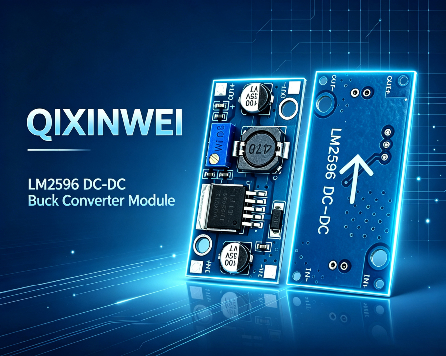
LM2596 LM2596S DC-DC Buck Converter Step Down Module——3.3V 5V 12V Adjustable Power Supply
What Is an LM2596 Module?
If you are building an electronic project that requires a stable lower voltage from a higher voltage source, you may have come across the LM2596 module So, what is an LM2596 module used for?
In simple terms, an LM2596 module is a DC-DC buck converter (step-down) power supply board designed to convert a higher input voltage (typically up to 40V) to a lower, stable output voltage. The module is built around the LM2596 switching regulator IC, originally introduced by Texas Instruments as part of the SIMPLE SWITCHER® family.
A typical LM2596 module takes a DC input voltage ranging from 4.5V to 40V and steps it down to a regulated output. Available versions include fixed outputs of 3.3V, 5V, and 12V, as well as an adjustable output version that can be set from approximately 1.23V to 37V. The module can deliver up to 3A of output current.
This is why you can find LM2596 modules in Arduino and ESP32 projects, DIY power supplies, automotive electronics, battery chargers, industrial control systems, communication equipment, and many other applications that require efficient voltage conversion.
However, there is an important detail that is often overlooked: not every LM2596 module is created equal. The module's performance depends on the quality of the inductor, diode, capacitors, PCB layout, and whether the IC is genuine or counterfeit.
LM2596 Brand, Product and Model
The main component on the board is the LM2596 buck converter IC. LM2596 is a widely used step-down switching regulator that integrates a power switch, oscillator, error amplifier, and output voltage detection circuit.
The product commonly called an LM2596 module, LM2596 buck converter, LM2596 step-down module, or LM2596 power supply module is actually a small PCB built around the LM2596 IC. Depending on the manufacturer, the PCB may include different inductors, diodes, capacitors, input/output terminals, potentiometers (for adjustable versions), and LED indicators.
LM2596 vs LM2596S: The difference between LM2596 and LM2596S primarily lies in the package. LM2596 typically refers to the TO-220 through-hole package, while LM2596S refers to the TO-263 (DDPAK) surface-mount package. Functionally, they are the same — the "S" simply indicates the surface-mount package variant.
Common fixed output models include:
LM2596S-3.3 — fixed 3.3V output, ideal for 3.3V logic circuits
LM2596S-5.0 — fixed 5V output, the most common version for microcontrollers and sensors
LM2596S-12 — fixed 12V output, suitable for industrial control and motor drive applications
LM2596S-ADJ — adjustable output from 1.23V to 37V via external resistors
This means that “LM2596 module” does not represent one completely standardized PCB design. Two boards may both be sold as LM2596 modules while having different components, output configurations, or PCB layouts.
For procurement and engineering projects, it is therefore better to check the actual schematic and component configuration rather than relying only on the words “LM2596 module.”
LM2596 Module Main Parameters
For a common LM2596 step-down module, the basic electrical specifications are as follows:
| Parameter | LM2596 DC-DC Buck Converter Module |
|---|---|
| Input Voltage | 3.2V~40V |
| Output Voltage | 1.25V~35V |
| Output Current | Up to 3A |
| Switching Frequency | 65 kHz |
| Efficiency | 92% |
| Operating Temperature | -45°C to +85°C |
The LM2596 uses a buck (step-down) switching topology. During operation, the internal switch turns on and off at 150 kHz, storing energy in an inductor and releasing it to the output. This switching approach is much more efficient than linear regulation, especially when the input-to-output voltage difference is large.
The module typically requires only four external components: an input capacitor, an output capacitor, an inductor, and a Schottky diode. The adjustable version adds two feedback resistors to set the output voltage.
A typical LM2596 module can therefore be understood as three functional sections: the input filtering section, the LM2596 switching regulator section, and the output filtering section.
How Does an LM2596 Module Work?
The working principle is easier to understand than it may first appear.
When a DC input voltage (4.5V to 40V) is applied, the LM2596's internal oscillator generates a 150 kHz fixed-frequency PWM signal. This signal drives the internal power switch. When the switch is ON, current flows through the inductor, storing energy in its magnetic field. When the switch turns OFF, the inductor releases this stored energy through the Schottky diode to the output.
The feedback pin (FB) monitors the output voltage through a resistor divider network. The internal error amplifier compares the feedback voltage with a 1.23V reference and adjusts the PWM duty cycle to maintain a stable output. This closed-loop regulation ensures that the output voltage remains constant despite changes in input voltage or load current.
For fixed output versions (3.3V, 5V, 12V), the feedback divider is built into the IC. For the adjustable version (ADJ), external resistors are required.
The module also includes built-in protection features:
Current limiting — protects against output short circuits and overloads
TTL shutdown capability — allows external control of the output
This simple yet effective switching regulation process is one of the main reasons the LM2596 module has become so popular in DIY electronics and industrial applications.
What Is an LM2596 Module Used For?
The most common use of an LM2596 module is stepping down a higher voltage to a lower, regulated voltage for powering electronic devices.
One of the most popular examples is converting a 12V or 24V automotive/industrial power supply down to 5V or 3.3V for microcontrollers, sensors, and other digital circuits. For instance, in a car, the battery voltage can range from 12V to 14.4V — an LM2596 module can provide a stable 5V output to power an Arduino or ESP32 project.
Another common example is powering a device from a higher-voltage battery pack. If you have a 24V battery system but need to power 5V logic, an LM2596 module provides an efficient solution.
The same idea can be used for:
DIY bench power supplies — adjustable output from 1.23V to 37V
Battery chargers — providing regulated voltage for charging circuits
LED lighting — stepping down voltage for LED drivers
Communication equipment — stable power for radio and networking devices
LCD displays and TVs — providing panel power
LM2596 Module Typical Applications
1. Arduino and ESP32 Projects
Portable microcontroller projects often need a stable 5V or 3.3V supply. An LM2596 module can efficiently convert a 12V or 24V source down to the required voltage. For example, an ESP32-based environmental sensor powered from a 12V battery can use an LM2596-5.0 module to provide clean 5V power.
2. Automotive Electronics
Vehicles operate on 12V or 24V electrical systems. LM2596 modules are widely used to power dash cameras, GPS trackers, USB chargers, and other in-vehicle electronics. The wide input voltage range handles the voltage fluctuations common in automotive environments.
3. DIY Variable Power Supplies
The adjustable LM2596S-ADJ version is popular for building variable bench power supplies. With a potentiometer, the output can be adjusted from 1.23V to 37V, making it useful for testing and prototyping various circuits.
4. Battery-Powered Devices
For battery-powered IoT devices, sensors, and portable instruments, an LM2596 module can efficiently regulate battery voltage to the required level. The high efficiency (up to 90%) helps extend battery life.
5. Industrial and Communication Equipment
LM2596 modules are used in industrial control panels, communication devices, and other equipment that requires stable, efficient voltage conversion from higher-voltage supplies.
Fixed Output vs Adjustable Output
This is one of the most important choices when buying an LM2596 module.
Fixed output versions (LM2596-3.3, LM2596-5.0, LM2596-12) provide a preset, stable voltage. They are simple to use — just connect the input and the output is ready. These are ideal when you know exactly what voltage you need.
Adjustable versions (LM2596-ADJ) allow you to set the output voltage anywhere from 1.23V to 37V using external resistors or a potentiometer. This provides maximum flexibility for prototyping and applications where the voltage requirement may change.
In other words:
Fixed LM2596 = simple, set-and-forget voltage regulation
Adjustable LM2596 = flexible, tunable voltage regulation
If you are building a project with a known voltage requirement (e.g., 5V for Arduino), a fixed version is simpler and more reliable. If you are building a variable power supply or prototyping multiple projects, the adjustable version offers greater versatility.
LM2596 vs Other Voltage Regulation Solutions
The LM2596 is popular because it is simple, efficient, and inexpensive, but it is not the best solution for every power supply application.
Compared with linear regulators (like the 7805), the LM2596 is much more efficient, especially when the input-to-output voltage difference is large. A linear regulator dissipates the voltage difference as heat, while a switching regulator like the LM2596 converts it efficiently.
Compared with more advanced DC-DC converters, the LM2596 has a lower switching frequency (150 kHz) and may require larger external components. Newer converters operate at higher frequencies, allowing smaller inductors and capacitors.
Compared with module-based solutions, the LM2596 module is a complete, ready-to-use solution that requires no additional design work. This makes it ideal for hobbyists and quick prototypes.
For a basic step-down application with 3A or less output current, LM2596 is often sufficient. For applications requiring higher current, higher efficiency, smaller size, or more advanced features (like synchronous rectification or soft-start), a more modern converter may be a better choice.
The most important question is therefore not “Is LM2596 good?” but rather “Does LM2596 match the input voltage, output voltage, current requirement, and efficiency needs of my application?”
Can LM2596 Be Replaced?
Yes. An LM2596 can be replaced by other DC-DC buck converters, but the correct replacement depends on the project requirements.
For a simple step-down application with similar specifications (up to 40V input, up to 3A output, 150 kHz switching frequency), another buck converter IC can potentially replace LM2596.
If you need higher efficiency, a synchronous buck converter may be a better alternative because it replaces the external Schottky diode with a low-resistance MOSFET, reducing losses.
If you need higher switching frequency, a modern converter operating at 500 kHz or higher allows smaller external components.
If you need higher input voltage, the LM2596HV version supports up to 60V input.
However, replacement should never be based only on the words “3A buck converter.” Engineers should compare input voltage range, output voltage options, output current capability, switching frequency, efficiency, thermal performance, package, PCB layout, and component availability.
A Practical Point Many LM2596 Users Miss
The biggest misunderstanding about the LM2596 module is that a small PCB with a few components does not automatically mean a high-quality power supply.
A module may have an LED indicator, input/output terminals, and a potentiometer, but you still need to verify the quality of each component.
Counterfeit ICs are common in cheap modules. Genuine LM2596 ICs switch at 150 kHz — counterfeit ones may switch at 50 kHz or lower, reducing efficiency and increasing heat.
Another common mistake is assuming that “3A output” is always achievable. The 3A rating is the IC's maximum capability under ideal conditions with proper heatsinking. In practice, the achievable output current depends on the input voltage, output voltage, ambient temperature, PCB copper area, and component quality.
The LM2596 is a switching regulator, but it still generates heat — especially when the input-to-output voltage difference is large and the output current is high. Under heavy load, the module surface temperature can reach 80°C to 100°C. Proper heatsinking (PCB copper area, external heatsink, or airflow) is essential for reliable operation.
PCB layout also matters. Wide copper traces, proper grounding, and short switch-node connections reduce noise and improve performance.
LM2596 Module FAQ
Q1: What is an LM2596 module used for?
An LM2596 module is mainly used to step down a higher DC voltage (up to 40V) to a lower, regulated output voltage (3.3V, 5V, 12V, or adjustable 1.23V–37V) at up to 3A. It is commonly used in Arduino/ESP32 projects, automotive electronics, DIY power supplies, and industrial applications.
Q2: Can LM2596 charge a battery?
The LM2596 is a voltage regulator, not a dedicated battery charger. While it can provide regulated voltage for charging circuits, it does not include the constant-current/constant-voltage charging algorithm required for proper battery charging. A dedicated battery charger IC should be used for battery charging applications.
Q3: What is the difference between LM2596 and LM2596S?
The difference is primarily the package. LM2596 typically refers to the TO-220 through-hole package, while LM2596S refers to the TO-263 (DDPAK) surface-mount package. Functionally, they are identical.
Q4: What is the maximum output current of an LM2596 module?
The LM2596 IC can deliver up to 3A under proper conditions. However, the actual achievable current depends on the input voltage, output voltage, heatsinking, and component quality. In practice, 2A to 2.5A is often more realistic for continuous operation without additional heatsinking.
Q5: Why does my LM2596 module get hot?
The LM2596 generates heat during operation, especially when the input-to-output voltage difference is large and the output current is high. Under heavy load, the module surface can reach 80°C to 100°C. Improving heatsinking (PCB copper area, external heatsink, or airflow) can help reduce temperatures. Counterfeit ICs may also generate more heat due to lower efficiency.
Q6: Can LM2596 step up voltage (boost)?
No. The LM2596 is a buck (step-down) converter only. It cannot step up voltage. For boost applications, a separate boost converter is required.
Q7: What is the input voltage range for LM2596?
The standard LM2596 accepts 4.5V to 40V input. The HV version (LM2596HV) accepts up to 60V. The input voltage must always be higher than the desired output voltage.
Q8: How do I choose an LM2596 module?
First confirm your input voltage range, required output voltage, and maximum load current. Then choose between fixed output (simpler) and adjustable output (more flexible). Check the quality of components — a genuine LM2596 IC, a proper inductor (33µH–47µH, ≥3A), a Schottky diode (e.g., SS34), and low-ESR capacitors. Consider the PCB layout and heatsinking capability for your application.
Q9: What is the difference between fixed and adjustable LM2596?
Fixed versions (3.3V, 5V, 12V) have a preset output voltage and require no external feedback resistors. The adjustable version (ADJ) requires external resistors to set the output voltage from 1.23V to 37V. Fixed versions are simpler and more reliable; adjustable versions offer greater flexibility.
Q10: Is LM2596 suitable for commercial products?
It can be suitable for prototypes and some simple commercial products, but commercial designs should not select a module purely because it is inexpensive. The designer should verify the actual IC (genuine vs counterfeit), component quality, thermal performance, input/output specifications, EMI considerations, certifications, and long-term supply stability.
Is LM2596 Module a Good Choice?
The LM2596 module remains popular because it solves a very specific problem extremely well: efficiently stepping down a higher DC voltage to a lower, regulated voltage at up to 3A.
For a DIY Arduino power supply, automotive electronics project, ESP32 sensor node, or variable bench supply, an LM2596 module can significantly simplify the power stage. The fixed versions provide simple, reliable regulation, while the adjustable version offers flexibility for prototyping.
But LM2596 should not be viewed as a universal power solution. It is a buck converter designed for step-down applications only, and it does not replace a boost converter, battery charger, or more advanced power management IC.
For engineers and buyers, the real selection criteria should be input voltage range, output voltage, output current, efficiency, thermal performance, component quality, and long-term supply stability rather than simply searching for a “3A LM2596 module.”
If you are developing a new battery-powered product, looking for LM2596 modules, DC-DC converter ICs, or other electronic components, or facing component shortages and need alternative parts, QIXINWEI can support component sourcing, BOM matching, model comparison, and supply-chain solutions. For engineering projects that require stable supply rather than simply the lowest unit price, selecting the right component configuration at the beginning can save much more time during testing and mass production.
0users like this.
